


 Deutsch
 English
 Italiano
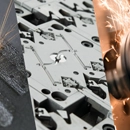
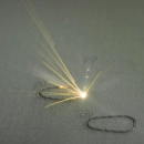









Selective Laser Melting (SLM): Metal 3D Printing
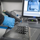
In selective laser melting (SLM, also known as laser powder bed fusion), fine metal powder is applied in thin layers to a build plate and melted by a laser exactly where the part is to be created. The metal solidifies and bonds with the layer below. Layer by layer, this produces high-density metal parts directly from the 3D data.
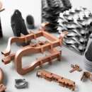
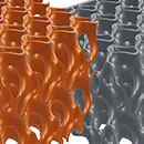
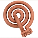
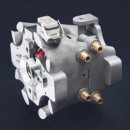
Because no tooling is required and the part is built up layer by layer, geometries that are difficult or impossible to machine become possible – such as internal cooling channels, lattice structures or several functions in one part. PROTIQ manufactures in laser melting itself, including tool inserts with conformal cooling and copper parts such as inductors. On the PROTIQ Marketplace, you upload your 3D data, choose the material and usually see the price and production time right away.
Laser melting at a glance
- Principle
- Powder bed: a laser melts metal powder layer by layer
- Materials
- including tool and stainless steel, aluminum, copper, brass, zinc alloy, titanium
- Support structures
- required – they connect the part to the build plate
- Accuracy
- depending on the material, e.g. ±0.7 %, at least ±0.1 mm
- Minimum wall thickness
- 0.4–0.6 mm, depending on the material
- Surface after sandblasting
- Ra 2.5–10 µm
- Post-processing
- heat treatment, machining, blasting, polishing
- Quantity
- single part to small series
Guide values, not guaranteed properties. The information provided by the supplier in the ordering process or in the quote is binding.
How it works
How does selective laser melting work?
A recoater spreads a thin layer of metal powder over the build plate. Scanner optics guide the laser beam across the powder layer and fully melt the metal wherever the cross-section of the part lies. The build platform then lowers by one layer thickness and the process repeats. The build chamber is filled with inert gas so that the metal does not oxidize.
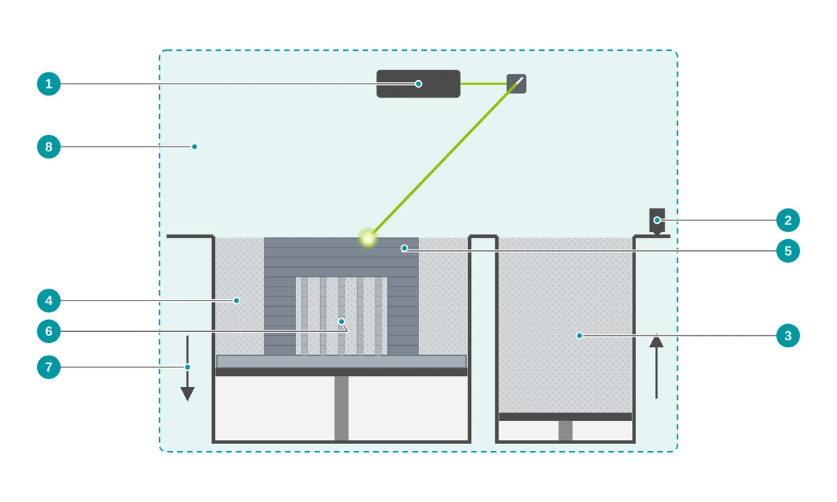
- 1 Laser with scanner optics guides the beam across the powder layer
- 2 Recoater applies a new layer of powder
- 3 Powder supply
- 4 Powder bed of metal powder
- 5 Part, melted layer by layer
- 6 Support structures connect the part to the build plate
- 7 Build platform lowers after each layer
- 8 Build chamber with inert gas so that the metal does not oxidize
- Preparing the data The 3D model is oriented on the build plate, given support structures and sliced into thin layers.
- Applying powder The recoater spreads a thin, even layer of metal powder.
- Melting The laser melts the powder along the cross-section. The platform then lowers and the next layer follows.
- Depowdering After printing, loose powder is removed – including from internal channels.
- Separating and removing supports The part is separated from the build plate and the support structures are removed.
- Post-processing Depending on the material and requirements, this can include heat treatment, sandblasting, machining of functional surfaces or polishing.
Laser melting on video
The video shows how metal parts are produced by selective laser melting.
After sieving, a large share of the unmelted powder can be reused.
↑ Back to overviewSLM or CNC?
What is the difference between laser melting and CNC milling?
CNC milling removes material from a solid block, while laser melting builds the part up layer by layer. Laser melting plays to its strengths with complex geometries – such as internal channels or lattice structures. Milling is suited to prismatic parts and tight tolerances. The two often complement each other: functional surfaces of printed parts are finished by machining.
| Laser melting (SLM) | CNC milling | |
|---|---|---|
| Principle | Built up layer by layer from metal powder | Removal from solid material |
| Geometry | internal channels, cavities and lattice structures are possible | limited by tool access |
| Tooling and fixtures | no part-specific tooling; instead, support structures that are removed after printing | milling tools and fixtures |
| Surface | slightly rough after sandblasting; functional surfaces are finished | smooth, depending on machining |
| Typical use | complex parts, function integration, lightweight design, tool inserts | prismatic parts, tight tolerances, larger quantities |
Which process suits your part better depends on geometry, material, tolerances and quantity. Upload your file and see the available offers in the configurator – or contact us if you would like to compare processes.
↑ Back to overviewAdvantages
What are the advantages of laser melting?
Laser melting produces high-density metal parts directly from the 3D data. It makes geometries possible that can hardly be produced conventionally and processes a wide range of materials – from tool steel through aluminum and titanium to copper.
Great design freedom
Undercuts, cavities and internal channels are printed directly – without tooling or fixtures. Cavities need openings for depowdering.
Conformal cooling
Cooling channels in tool inserts follow the contour of the part instead of being drilled in straight lines.
Integrating functions
Several individual parts can be combined into one – which can save assembly and joining work.
Lightweight design
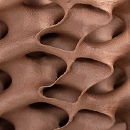
Lattice and honeycomb structures reduce weight wherever no material is needed.
Conductive copper
Pure copper achieves an electrical conductivity of 58 MS/m – for example for inductors and busbars.
No tooling, from one part
No mold, no mold costs – from prototypes and spare parts to small series.
Materials
Which materials are available for laser melting?
Laser melting processes metal powders – including tool and stainless steels, aluminum, copper and copper alloys, brass, zinc alloys, titanium and magnesium.
The choice of material affects strength, hardness, conductivity, weight, corrosion resistance and price. Steels such as MS1, CX or PH1 can be made considerably stronger and harder by heat treatment. You can see which materials are currently available in the configurator after uploading your file – where you will also find the suppliers’ data sheets.
Tool and stainless steel
For tool inserts, functional parts and corrosion-resistant parts.
- Tool steel MS1 (1.2709)
- Stainless steel CX
- Stainless steel PH1 (1.4540) and 1.4542
- Stainless steel 316L (1.4404)
Copper
For parts that conduct electricity or heat.
- Pure copper
- CuCr1Zr
- RS copper
- CuNi2SiCr
Brass and zinc alloy
For decorative parts and functional prototypes made of production materials.
- RS brass
- Zamak 5
Titanium and magnesium
For high-strength or particularly lightweight parts.
- Titanium Ti6Al4V
- Magnesium alloy WE43
Other materials
Depending on the supplier, other materials are available or possible on request – you can see the current range in the configurator.
Properties: tool and stainless steel
| Material | Density (g/cm³) | Tensile strength (MPa) | Yield strength Rp0.2 (MPa) | Elongation at break (%) | Hardness |
|---|---|---|---|---|---|
| Tool steel MS1 (1.2709) | 8–8.1 | 1,100 / 2,030 | 1,000 / 1,950 | 9 / 4 | 33–37 / 53 HRC |
| Stainless steel CX | 7.7 | 1,080 / 1,730 | 840 / 1,660 | 14 / 6 | – / 50 HRC |
| Stainless steel PH1 (1.4540) | 7.7 | 1,200 / min. 1,340 | 950 / min. 1,200 | 17 / min. 10 | 30–35 / min. 40 HRC |
| Stainless steel 1.4542 | 7.7–7.8 | 1,100 / 1,150 | 750 / 1,050 | 13 / 18 | 35 / approx. 40 HRC |
| Stainless steel 316L (1.4404) | 7.9 | 670 / – | 570 / – | min. 30 / – | 85 HRB / – |
Properties: aluminum, titanium and magnesium
| Material | Density (g/cm³) | Tensile strength (MPa) | Yield strength Rp0.2 (MPa) | Elongation at break (%) | Notes |
|---|---|---|---|---|---|
| AlSi10Mg | 2.67 | 410 / 340 | 250 / 220 | 6 / 7 | Young’s modulus 65 GPa; thermal conductivity 103 W/(m·K) |
| Titanium Ti6Al4V (3.7164) | 4.41 | 1,090 | 1,000 | 13 | 41 HRC; max. service temperature approx. 350 °C |
| Magnesium alloy WE43 | 1.84 | 311 (Z: 265) | 270 (Z: 114) | 19 (Z: 10) | Young’s modulus 48 GPa (Z: 52 GPa); thermal conductivity 51.3 W/(m·K) |
Properties: copper, brass and zinc alloy
| Material | Density (g/cm³) | Tensile strength (MPa) | Elongation at break (%) | Electrical conductivity (MS/m) | Thermal conductivity (W/(m·K)) |
|---|---|---|---|---|---|
| Pure copper | 8.9 | 220 | 50 | 58 | 415 ± 10 |
| CuCr1Zr | 8.8–8.9 | – / 220 | – / 25 | 49 / 32 (edge / core) | 260 |
| RS copper | 8.7–8.9 | – | – | 51 / 32 (edge / core) | 265 |
| CuNi2SiCr | – | 251 / 595 | 34 / 15 | – | – |
| RS brass | 8.2–8.6 | 310 | 8 | 8 | – |
| Zamak 5 | 6.2–6.4 | 218 | 1.5 | – | 85 |
Values from the data sheets on the PROTIQ Marketplace (as of 01/2021 to 04/2026), without the ranges given in some cases; no properties are guaranteed. Where two values are given, the first refers to the as-built condition and the second to the condition after heat treatment, unless stated otherwise. For WE43, the first value refers to the horizontal direction (X-Y) and the value in brackets to the build direction (Z). The values come from different suppliers, were partly determined on standard geometries and may vary depending on the part, orientation, machine and parameters; they are therefore only comparable to a limited extent. The supplier’s information is binding.
SLM, DMLS, MS1, CX, PH1 and other process and material designations mentioned are trademarks or designations of their respective owners. They are mentioned only to describe the process or materials.
↑ Back to overviewTechnical data
Technical data and design guidelines
For most of the materials listed here, the accuracy is ±0.7 %, at least ±0.1 mm. The minimum wall thickness is 0.4 to 0.6 mm depending on the material, and the roughness after sandblasting is Ra 2.5 to 10 µm. The maximum part size depends on the machine.
| Feature | Value |
|---|---|
| Maximum part size | depends on the supplier’s machine; when you upload your file, the system automatically checks whether the part fits into the build chamber |
| Accuracy | ±0.7 %, at least ±0.1 mm for most of the materials listed here; may differ depending on supplier and material |
| Minimum wall thickness | 0.4–0.6 mm, depending on the material |
| Media-tight parts (pure copper, CuCr1Zr, RS copper) | wall thickness from 1 mm; leak test with 6 bar compressed air |
| Layer thickness | depending on material and machine, e.g. 30 or 60 µm |
| Roughness after sandblasting | Ra 2.5–10 µm, Rz 15–60 µm, depending on the material |
| Support structures | required, removed after printing |
Guide values, not guaranteed properties. The information provided by the supplier in the ordering process or in the quote is binding.
What to consider when designing your parts
- Overhangs and supports The flatter an overhang, the more likely it is to need supports. Supports have to be removed after printing – the surface is rougher at these points. Design overhangs as steep or self-supporting as possible.
- The powder has to come out Internal channels and cavities need openings so that loose powder can be removed. Fully enclosed cavities remain filled with powder.
- Observe the wall thickness Plan at least 0.4 to 0.6 mm, depending on the material. For media-tight parts made of pure copper, CuCr1Zr or RS copper, wall thicknesses from 1 mm are specified.
- Machining allowance for functional surfaces Fits, sealing surfaces and threads are usually finished by machining. Plan a machining allowance for this.
- Plan for heat treatment Some steels only reach their highest strength after heat treatment – MS1, for example, 2,030 instead of 1,100 MPa tensile strength. Specify the required condition when ordering.
- Avoid solid cross-sections Large, solid areas increase material use, build time and residual stresses. Where possible, cut-outs or lattice structures help.
Limits & alternatives
When is another process the better choice?
- Surface After sandblasting, the surface is slightly rough (Ra 2.5–10 µm). Smooth functional or sealing surfaces require machining or polishing.
- Support structures Overhangs need supports that are printed along with the part, firmly attached to it and have to be removed after printing. This increases the post-processing effort.
- Part size The size is limited by the machine’s build chamber. When you upload your file, the system automatically checks whether your part fits.
- Simple geometries in quantity For simple parts or large quantities, conventional processes such as milling or die casting are often more cost-effective.
| Process | Strengths | May be the better choice if … |
|---|---|---|
| CNC machining | Tight tolerances and smooth surfaces from solid material | … your part is prismatic or needed in larger quantities |
| Lithography-based Metal Manufacturing (LMM) | Small, very detailed metal parts | … your part is small and needs fine details |
| Zinc die casting | Cost-effective for large quantities | … you need many identical zinc parts |
| Laser sintering (SLS) | Plastic parts without support structures | … your part does not have to be made of metal |
Applications
What is laser melting used for?
Typical applications include tool inserts with conformal cooling, copper inductors and busbars, heat exchangers, lightweight components, spare parts and functional prototypes made of production materials.

Tool making
Tool inserts with conformal cooling whose channels follow the contour of the part.
To tool making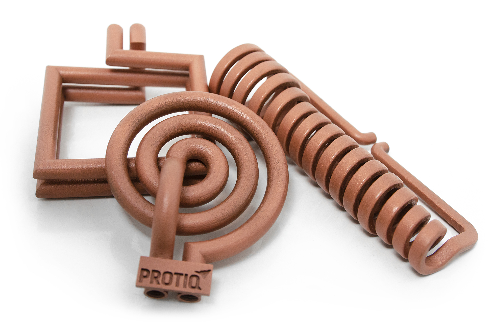
Inductors
Copper inductors with integrated cooling channels and a geometry adapted to the workpiece.
To inductors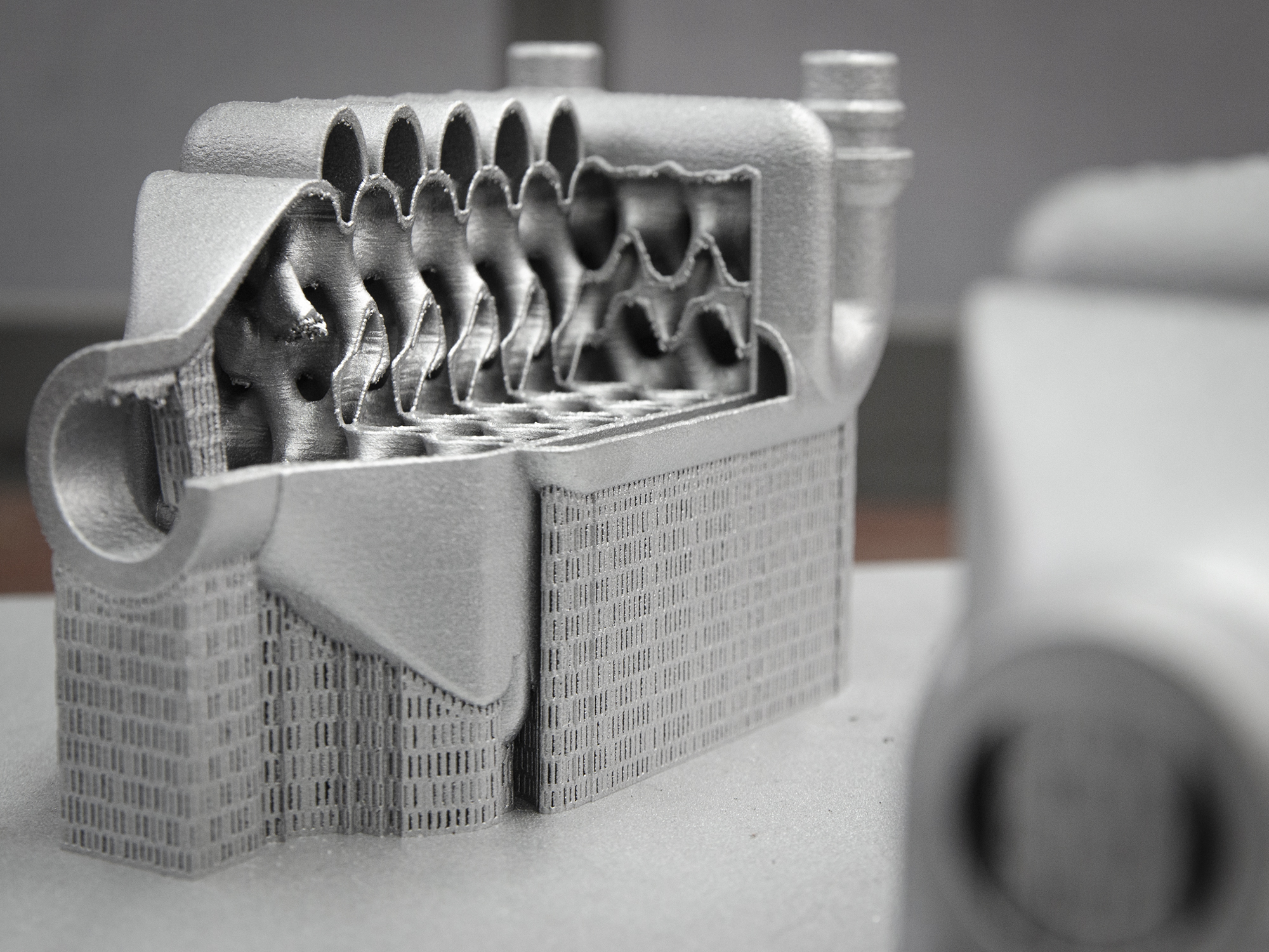
Heat exchangers
Compact heat exchangers and heat sinks with large surface areas in a small space.
To heat exchangersOrdering
How do I order laser-melted parts?
Upload your 3D file, choose the material and process, and see the available offers.
- Upload your file Upload your 3D data in the configurator. The system automatically checks whether the part fits into the build chamber.
- Choose the material Choose from over 160 materials and over 12 processes – for example AlSi10Mg in laser melting.
- Check the offer You usually see the price and production time of the available suppliers right away.
- Order You order directly online at the selected price.
If a material cannot be selected directly or you need a specific heat treatment, just send us a request.
↑ Back to overview
FAQ
Frequently asked questions about laser melting
What is selective laser melting?
Selective laser melting (SLM) is a powder bed 3D printing process for metal. A laser melts fine metal powder layer by layer wherever the part is to be created. This produces high-density metal parts directly from the 3D data.
What is the difference between SLM, DMLS and LPBF?
The terms describe the same basic principle: melting metal powder with a laser in a powder bed. The ISO/ASTM 52900 standard calls the process powder bed fusion of metals with a laser (PBF-LB/M); LPBF is a common short form. SLM and DMLS were originally names used by individual machine manufacturers and are often used interchangeably.
Which materials are available for laser melting?
On the PROTIQ Marketplace, you will currently find tool steel MS1, the stainless steels CX, PH1, 1.4542 and 316L, AlSi10Mg, pure copper, CuCr1Zr, RS copper, CuNi2SiCr, RS brass, Zamak 5, titanium Ti6Al4V and the magnesium alloy WE43, among others. You can see the current range in the configurator.
How accurate is laser melting?
For most of the materials listed here, the accuracy is ±0.7 %, at least ±0.1 mm. It may differ depending on the supplier and material. Functional surfaces with tight tolerances are usually finished by machining. The supplier’s information is binding.
How strong are laser-melted parts?
Depending on the material, they achieve high strength – tool steel MS1, for example, 1,100 MPa as built and 2,030 MPa after heat treatment. Properties may vary depending on orientation, part and parameters. Whether a part is suitable for your application should be checked by testing on a case-by-case basis.
Can laser-melted parts be post-processed?
Yes. Typical steps are heat treatment, sandblasting, machining of functional surfaces and polishing. You can see which options are available in the configurator or find out on request.
Can parts be made media-tight?
For pure copper, CuCr1Zr and RS copper, media tightness is specified from a wall thickness of 1 mm (leak test with 6 bar compressed air). For other materials, please contact us.
How much does a laser-melted part cost?
The price depends on factors such as part volume, size, material, support structures, post-processing and quantity. After uploading your file, you usually see the suppliers’ prices in the configurator right away.