

 Deutsch
 English
 Italiano







Lithography-based Metal Manufacturing (LMM): Small, Delicate Metal Parts
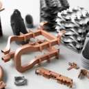
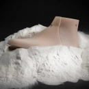
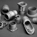
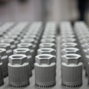
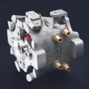
Lithography-based Metal Manufacturing (LMM) is a 3D printing process for small, delicate metal parts. A mixture of fine metal powder and photopolymer is applied layer by layer and exposed with a projector. The resulting part, the green part, is then debound and sintered – creating the metal part.
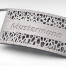
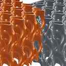
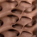
The projector exposure makes it possible to reproduce very fine structures. Because the unexposed material supports the part during printing, support structures are generally not required. LMM is therefore particularly suitable for small, delicate parts with fine details – for example for precision mechanics, tools or small parts with complex geometry. For larger metal parts, selective laser melting (SLM) is the obvious choice.
LMM at a glance
- Process principle
- Exposure of a metal powder–photopolymer mixture, followed by debinding and sintering
- Support structures
- generally none – the unexposed material supports the part
- Part size
- small, depending on the machine e.g. up to 70 × 45 × 100 mm
- Shrinkage during sintering
- parts approx. 20 % smaller, depending on the material
- Quantity
- Single part to small batch
Guide values, not guaranteed properties. The information provided by the supplier in the ordering process or in the quote is authoritative.
How it works
How does the LMM process work?
A mixture of metal powder and photopolymer, which is pasty at room temperature and becomes liquid when heated, is heated and applied as a thin layer to the build platform. A projector exposes the cross-section of the part, where the photopolymer cures. This is how the green part is built layer by layer. The photopolymer is then removed thermally (debinding) and the part is sintered.
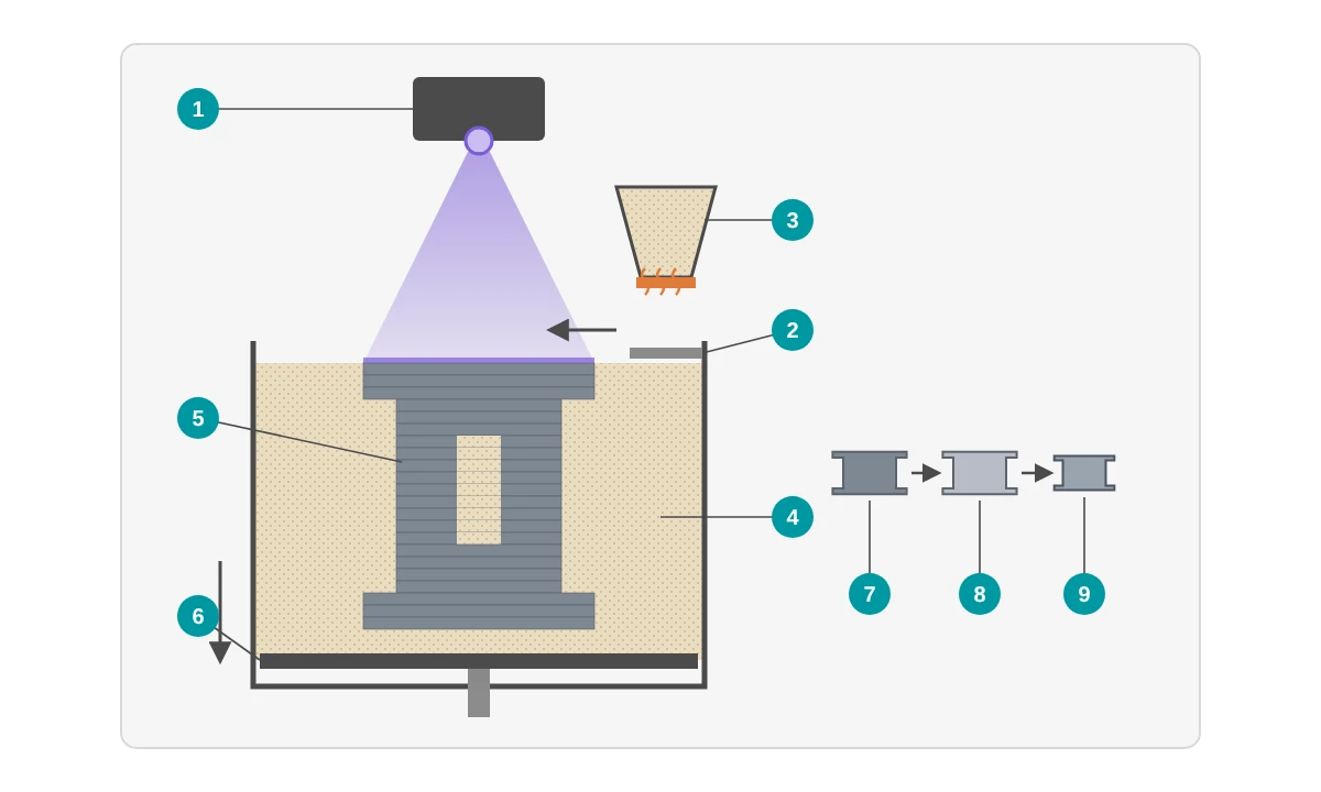
- 1 Projector exposes the cross-section of the current layer
- 2 Recoater applies a new layer of the heated mixture
- 3 Heated reservoir of metal powder and photopolymer
- 4 Unexposed material – becomes pasty as it cools and supports the part
- 5 Green part: exposed areas, cured layer by layer
- 6 Build platform lowers after each layer
- 7 Green part after printing
- 8 Debinding: the photopolymer is removed thermally
- 9 Sintering: the part densifies and shrinks to the intended dimensions
- Prepare data The 3D model is arranged in the build space – taking sintering shrinkage into account – and sliced into layers.
- Apply and expose The heated mixture is applied as a thin layer and the projector exposes the cross-section. This is repeated layer by layer.
- Remove the green part The material block is heated, and the unexposed material becomes liquid and flows off. It can be reused for further print jobs.
- Debinding The photopolymer is removed thermally from the green part.
- Sintering In the furnace, the metal powder densifies into the metal part. Sintered parts are approx. 20 % smaller than the green part (depending on the material).
- Finishing Depending on requirements, this is followed by micro-blasting or heat treatment, for example. The available options depend on the supplier.


LMM or SLM?
What is the difference between LMM and selective laser melting?
In selective laser melting, a laser melts the metal powder directly. In LMM, a mixture of metal powder and photopolymer is exposed, and the metal part is only created during sintering. LMM is particularly suitable for small, delicate parts, while laser melting is also suitable for larger functional parts.
| LMM | Laser melting (SLM) | |
|---|---|---|
| Process principle | Exposure of a powder–photopolymer mixture, then debinding and sintering | Laser melts metal powder directly |
| Support structures | generally none | generally required, removed after printing |
| Part size | small parts | larger parts as well |
| Typical use | delicate small parts, fine details | functional parts, tool inserts, lightweight design |
Which process suits your part better depends on size, geometry, material and quantity. Upload your file and see the available offers in the configurator – or contact us if you would like to compare processes.
↑ Back to overviewAdvantages
What are the advantages of LMM?
LMM produces small metal parts with fine details and smooth surfaces – generally without support structures that would have to be removed.
Fine details
With a lateral resolution of e.g. 35 µm and layer thicknesses from 10 µm, fine structures can be reproduced.
Smooth surfaces
With 316L, a surface quality of up to Ra 2 µm can be achieved in the as-sintered state.
Generally no support structures
The unexposed material supports the part. Support structures therefore generally do not have to be removed.
Parts placed freely in the build space
Because no supports are needed, parts can be arranged three-dimensionally in the build space.
Stress-free microstructure (316L)
With 316L, the sintering-based production results in a stress-free, annealed microstructure.
Reusable material
Unexposed material flows off after printing and can be reused for further print jobs.
Materials
Which materials are available for LMM?
On the PROTIQ Marketplace, LMM is currently offered with stainless steels, such as the corrosion-resistant 316L and the precipitation-hardening 17-4PH.
You can see which materials are currently available in the configurator after uploading – where you will also find the suppliers’ datasheets.
Stainless steel 316L (1.4404)
Austenitic chromium-nickel-molybdenum steel with low carbon content – corrosion-resistant and weldable.
Stainless steel 17-4PH (1.4542)
Stainless, martensitic, precipitation-hardening chromium-nickel-copper steel with high strength and toughness. Its properties can be adjusted by heat treatment.
Material data compared
| Material | Density (g/cm³) | Tensile strength Rm (MPa) | Yield strength Rp0.2 (MPa) | Young’s modulus (GPa) | Elongation at break (%) | Roughness (µm) |
|---|---|---|---|---|---|---|
| Stainless steel 316L (1.4404) | – | 664 ± 47 | 257 ± 26 | 176 ± 48 | 75 ± 4 | up to Ra 2 (as sintered) |
| Stainless steel 17-4PH (1.4542) | 7.7 (rel. density 96–99.5 % with standard parameters) | – | – | – | – | Ra 5 ± 1 (as sintered), Ra 3 ± 2 (micro-blasted) |
Values from the datasheets on the PROTIQ Marketplace (as of 2023); they do not constitute guaranteed properties. The datasheet for 17-4PH contains no mechanical values; the properties can be adjusted by heat treatment. The values depend on process control and part geometry. The supplier’s information is authoritative.
↑ Back to overviewTechnical data
Technical data and design guidelines
LMM is designed for small parts, depending on the machine e.g. up to 70 × 45 × 100 mm. Depending on the machine, the lateral resolution is e.g. 35 µm and the layer thickness 10 to 60 µm. Sintered parts are approx. 20 % smaller than the green part – the shrinkage is usually taken into account during data preparation.
| Feature | Value |
|---|---|
| Maximum part size | depending on the machine, e.g. 70 × 45 × 100 mm; when you upload, the system automatically checks whether the part fits into the build space |
| Lateral resolution | depending on the machine e.g. 35 µm |
| Layer thickness | depending on the machine e.g. 10–60 µm |
| Shrinkage during sintering | parts approx. 20 % smaller, depending on the material; the shrinkage is usually taken into account during data preparation |
| Surface | 316L up to Ra 2 µm as sintered; 17-4PH Ra 5 ± 1 µm as sintered, Ra 3 ± 2 µm after micro-blasting |
| Support structures | generally none |
Guide values, not guaranteed properties. The information provided by the supplier in the ordering process or in the quote is authoritative.
What to consider when designing
- Think small LMM plays to its strengths with small parts with fine details. For larger parts, laser melting is the more likely option.
- Uniform wall thicknesses The part shrinks during sintering. Uniform wall thicknesses and smooth transitions can help reduce dimensional deviations.
- The material has to get out Cavities and channels need openings so that the unexposed material can flow off after printing.
- Avoid bulky areas Very bulky cross-sections can make debinding more difficult. Please clarify bulky parts with us in advance.
- Clarify functional surfaces For fits with tight tolerances, please contact us before ordering – depending on requirements, post-processing may be necessary.
- Choose the material according to purpose 316L for corrosion-resistant, weldable parts, 17-4PH for parts that are to become stronger or harder through heat treatment.
Limits & alternatives
When is another process the better choice?
- Part size LMM is not suitable for medium-sized and large parts. Larger metal parts can be produced with laser melting, for example.
- Material selection Stainless steels are currently offered. For other metals, processes such as laser melting are an option; you can see the available materials in the configurator.
- Shrinkage Sintered parts are approx. 20 % smaller than the green part; the shrinkage is usually taken into account during data preparation.
- Density For 17-4PH, the achievable relative density with standard parameters is 96 to 99.5 %. If parts need to be pressure-tight, please clarify suitability with us in advance.
| Process | Strengths | May be the better choice if … |
|---|---|---|
| Selective laser melting (SLM) | Metal parts in larger dimensions as well, wide choice of materials | … your part is larger or you need a different material |
| CNC machining | Tight tolerances and smooth surfaces from solid material | … your part has a simple shape or is needed in larger quantities |
| Stereolithography (SLA) | Fine details and smooth surfaces in plastic | … your part does not have to be made of metal |
Lithography-based Metal Manufacturing (LMM) and other process and material names mentioned are trademarks or designations of their respective owners. They are mentioned only to describe the process or materials.
↑ Back to overviewApplications
What is LMM used for?
LMM is suitable for small, complex metal parts – for example for precision mechanics, prototypes and one-offs, small tools and tool inserts or small batches with many variants. Sinter-based processes are also used in fields such as medical technology, aerospace or jewelry.
↑ Back to overviewOrdering
How do I order parts made with LMM?
Upload your 3D file, choose material and process and see the available offers.
- Upload file Upload your 3D data in the configurator. The system automatically checks whether the part fits into the build space.
- Choose material Choose from more than 160 materials and more than 12 processes – for example 316L with the LMM process.
- Check the offer As a rule, you immediately see the price and production time of the available suppliers.
- Order You order directly online at the selected price.
If a material cannot be selected directly, feel free to ask us.
↑ Back to overviewFAQ
Frequently asked questions about LMM
What is Lithography-based Metal Manufacturing (LMM)?
LMM is a 3D printing process for metal. A mixture of metal powder and photopolymer is applied layer by layer and exposed with a projector. The resulting green part is then debound and sintered.
What is the difference between LMM and SLM?
In selective laser melting, a laser melts the metal powder directly, which generally requires support structures. In LMM, a powder–photopolymer mixture is exposed and the part is then sintered – generally without support structures. LMM is suitable for small, delicate parts, SLM also for larger ones.
Which materials are available for LMM?
On the PROTIQ Marketplace, you will currently find stainless steels such as 316L (1.4404) and 17-4PH (1.4542). You can see the current selection in the configurator.
How large can LMM parts be?
LMM is designed for small parts, depending on the machine e.g. up to 70 × 45 × 100 mm. When you upload, the system automatically checks whether your part fits into the build space.
How smooth are LMM parts?
With 316L, a surface quality of up to Ra 2 µm is possible in the as-sintered state. With 17-4PH, it is Ra 5 ± 1 µm as sintered and Ra 3 ± 2 µm after micro-blasting. The supplier’s information is authoritative.
Why do LMM parts shrink?
During debinding, the photopolymer is removed; during sintering, the metal powder densifies. Sintered parts are approx. 20 % smaller than the green part (depending on the material). The shrinkage is usually taken into account during data preparation.
How much does an LMM part cost?
The price depends on factors such as part volume, size, material, post-processing and quantity. After uploading your file, you will usually see the suppliers’ prices immediately in the configurator.