


 Deutsch
 English
 Italiano






3D-Printed Copper Inductors
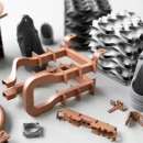
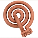
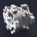
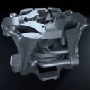
PROTIQ manufactures inductors for induction heating from 100% copper using selective laser melting (SLM) – in a single piece, without brazed or welded joints and directly from CAD data. This makes complex coil shapes adapted to the workpiece possible, including integrated cooling channels. Production can start as soon as the order is received, and you receive your coils within a few days.
For simple coil shapes, use the free inductor configurator. For existing designs, upload your CAD data. For special shapes, our CAD and manufacturing experts support you – up to simulation-based optimization.

Simple coil shape
Configure your inductor online
Six basic shapes for internal and external field inductors, adapted using a modular system. The price is calculated automatically online.
Go to the inductor configuratorExisting design
Upload CAD data
Upload your inductor geometry, get an automatically generated quote in just a few clicks and place your order directly.
Upload 3D dataSpecial shape & optimization
Discuss your project
For complex geometries, special requirements or simulation-based optimization, we advise you personally.
Contact us- 100% copperelectrical conductivity of up to 59 MS/m (≈ 101% IACS)
- Factor of 4 to 6longer service life of induction coils
- A few daysfrom order to delivery
Basics
What is induction heating?
Induction heating is a widely used industrial heating process: a workpiece made of electrically conductive material, such as steel or cast iron, is placed in the magnetic field of an induction coil – the inductor – and heated within a very short time. The heat is generated directly in the part, not in a furnace or by a flame.
Strong alternating currents are used to generate the magnetic field. The coils are therefore cooled from the inside with cooling water and are usually hollow. Because the heat is generated directly in the part, the process is very efficient and has a high degree of efficiency. It can also be controlled very precisely and reproduced reliably via the current and the generator frequency.
Typical applications
- Surface hardening: Highly stressed parts such as automotive transmission components are heated locally and then quenched abruptly. This increases the hardness and strength of the surface.
- Induction brazing: Two parts are heated precisely and joined with a filler metal. Precise, uniform heating to the target temperature is decisive for the quality of the joint.
- Hot forging: Parts are heated before forming – with a precise inductor, only where it is needed.

The inductor – the heart of induction heating
Heat is only generated where the electromagnetic eddy currents are induced into the workpiece. The more precisely the inductor is matched to the geometry of the part to be heated, the more precisely the heat distribution can be controlled. This is why every part design needs an individually developed inductor.
↑ Back to overviewManufacturing compared
Why 3D print inductors?
Conventional copper inductors are made by bending and brazing or are milled from solid material and then joined. Both are time-consuming and limit the geometry – and brazed or welded joints are a potential weak point in operation. With 3D printing, the inductor is produced in a single piece, without joints and exactly according to the CAD data.
| Bending & brazing | CNC milling & joining | 3D printing (SLM) | |
|---|---|---|---|
| Production | Manual bending and brazing | CNC milling from solid material, followed by welding or brazing of the individual parts | Selective laser melting directly from CAD data, in a single piece |
| Geometry | Only relatively simple geometries | More complex geometries | Complex geometries adapted to the workpiece, including rectangular or flattened profiles |
| Cooling channels | – | Require the individual components to be joined | Directly integrated |
| Joints | Brazed joints | Welded or brazed joints – a potential weak point in operation | None – seamless design |
| Effort | Very time-consuming, low repeatability | Time-consuming and cost-intensive | Automated, without additional tooling, high repeatability |
Your benefits with 3D-printed inductors
- Individual inductor geometries without tooling costs
- Freedom in cross-sections and coil shapes – including individual profiles and minimal bending radii
- Integrated cooling and flow channels and very compact designs
- Exact implementation of CAD data with high repeatability
- Higher process stability and service life thanks to the seamless design without brazed seams
- Optimized coil shapes for more precise heating and shorter cycle times
- Production within a few days, even with frequently changing workpieces
“The cycle life of induction coils is an essential criterion for economic efficiency and process reliability in the application. In close cooperation with PROTIQ, we were able to increase the service life of induction coils by a factor of 4 to 6 through optimizations in the areas of material, inductor design and adaptation of process parameters during sintering. Compared to conventional manufacturing processes in inductor construction (such as bending, milling, turning and soldering), this has resulted in a considerable advantage in terms of cost-effectiveness and design freedom.”
Andreas Häußler, IDEA GmbH
Material
Copper in 3D printing – a challenge
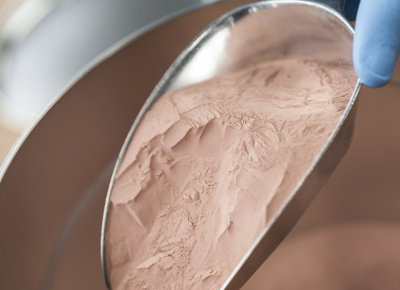
Copper reflects almost all of the radiation from conventional laser melting systems. Many 3D printing service providers therefore use alloys with a comparatively low copper content – but their conductivity is often unsatisfactory. PROTIQ has developed a process that makes it possible to process highly conductive copper additively.
PROTIQ manufactures components from 100% copper with electrical conductivities of up to 59 MS/m (≈ 101% IACS) at a density of 8.9 g/cm³. The process enables complex geometries and thus significantly expands the possibilities of inductor design – up to individual designs for your specific requirements.
You will find all copper materials – including the new pure copper low-O₂ – on our copper page.
↑ Back to overviewWhat should I consider when designing 3D-printed inductors?
The key factors are part size, wall thickness, internal diameter and the spacing between turns: inductors up to 250 × 250 × 280 mm are possible in a single piece, larger ones are segmented and joined. From a wall thickness of 1.0 mm, PROTIQ guarantees leak tightness up to 6 bar air pressure, and internal diameters from approx. 3 mm ensure that the build powder can be completely removed.
The guidelines apply to the phase in which your CAD data is being created. The values actually possible depend on the specific geometry.
| Criterion | Guideline | What to consider |
|---|---|---|
| Part size | 250 × 250 × 280 mm in a single piece | This is the maximum size of an inductor produced in a single piece on the build platform. Larger inductors are manufactured in segments and then joined – we are happy to coordinate with you on where best to place the joints. |
| Wall thickness and leak tightness | From 1.0 mm: leak tightness up to 6 bar air pressure guaranteed | Thinner walls from around 0.5 mm are feasible but depend strongly on the geometry – there is no leak-tightness guarantee for them. Very thin-walled inductors have already been manufactured successfully after prior consultation. |
| Internal diameter | From approx. 3 mm | Excess build powder must be completely removable from the interior. Below approx. 3 mm, this can no longer be reliably ensured; the required value depends on the coil geometry. |
| Spacing between turns | Approx. 1–2 mm | If support structures are required, they must be removable mechanically. The actual spacing required depends on the geometry. |
| Coil cross-section | Round, rectangular, flattened or freely shaped | All common cross-sections are possible, as are geometries adapted to the workpiece. Rectangular and flattened profiles offer particular design freedom. |
| Welded and brazed joints | Not required | Even complex geometries are produced in a single piece – joints, and with them potential weak points, are eliminated. Only inductors larger than the build space are joined from segments. |
| Connection blocks | Printed or combined | The inductor and connection blocks can be printed together. Often the most cost-efficient option: only the complex inductor head is 3D printed, while the connection blocks are manufactured conventionally and attached afterwards – without functional disadvantages. |
“In practice, it becomes evident that companies can significantly benefit from additive manufacturing when designing and using copper induction coils. In particular, short lead times, increased design freedom, achievable coil complexity and high repeatability create measurable advantages. The geometry of additively manufactured induction coils is not limited by conventional manufacturing restrictions, enabling the implementation of optimized coil designs. As a result, the efficiency of the heating process increases and cycle times are reduced – a clear competitive advantage.”
Max Wissing, PROTIQ GmbH
Inductor configurator
How do I configure an inductor online?
With the free inductor configurator, you choose one of six basic shapes and adjust parameters such as the number of turns, the coil diameter or the position of the connection using a modular system. The price is calculated automatically, and 3D printing production can start immediately after you order.
Conventionally, induction coils have to be designed and produced specifically for each application in a time-consuming process – it often takes weeks or even months from order receipt to completion. The configurator and tool-free 3D printing shorten this process to a few days. Printability of the configured 3D models is guaranteed.

Your application-specific inductor in four steps
-
 Step 1: Select a basic shapeChoose the optimal geometry for your requirements from six standard shapes for internal and external field inductors.
-
 Step 2: Configure the inductorDefine height, cross-section and diameter as well as the number of turns and the diameters and spacing of coils and channels.
-
 Step 3: Define the connection elementOptionally, add a holder to the inductor and define the dimensions of the base plate individually.
-
 Step 4: Complete your orderThe price of your configuration is calculated automatically online. You then order directly online.
Go to the inductor configurator
↑ Back to overviewSpecial shapes
Special shapes and simulation-based optimization
Conventionally, many trial geometries are usually produced and tested in real heating trials before the optimal coil is found – which is costly and time-consuming. With numerical simulation, the behavior of the coil in the process can instead be visualized and an optimized inductor geometry determined, which is then 3D printed from highly conductive copper.
How do simulation and optimization work?
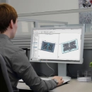
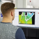
First, the heating process of your application is mapped in a simulation model – with the geometry of the inductor and the part as well as the boundary conditions and process parameters. Based on this, the thermal heating behavior of the part and the electromagnetic properties of the coil are examined, such as heating inside the part or the magnetic field that builds up.
The results allow a much more detailed analysis than real heating trials. This is how PROTIQ analyzes and optimizes existing inductors or determines the parameters for new heating processes. The optimized inductors heat quickly and precisely – for more accurate hardening patterns and shorter cycle times in series production.
How you benefit from simulation and 3D printing
- Insight into otherwise invisible process influences and their interactions
- Visualization and evaluation reveal optimization potential
- Fewer real tests with trial geometries – saving time and development costs
- Coils with ideal properties for your individual process
- Production of the optimized induction coils from pure copper within a few days
From conventional to optimized inductor in four steps


Free download
Brochure: highly conductive copper inductors
Everything about additive manufacturing with copper, induction heating, the inductor configurator and the simulation-based optimization of inductor geometries.
Your next inductor project
We support you in evaluating design options, manufacturing approaches and application possibilities for copper inductors. Our experts are happy to discuss your requirements and provide an individual assessment of your project.

Frequently asked questions about 3D-printed copper inductors
Why is copper used in 3D printing for inductors?
Copper has extremely high electrical and thermal conductivity. 3D printing makes it possible to produce complex inductor geometries seamlessly and without brazed joints, which increases efficiency and service life. PROTIQ uses a specially developed process to reliably manufacture 100% copper additively – with electrical conductivities of up to 59 MS/m (≈ 101% IACS).
What is the difference between pure copper and copper alloys in 3D printing?
Because copper reflects almost all of the radiation from conventional laser melting systems, many 3D printing service providers use alloys with a comparatively low copper content. Their conductivity is often unsatisfactory. PROTIQ, by contrast, processes 100% copper with conductivities of up to 59 MS/m.
How do I get a price for my inductor?
For simple coil shapes, the inductor configurator calculates the price automatically online. If you already have 3D CAD data, upload the inductor geometry and get an automatically generated quote in just a few clicks. For special shapes or simulation-based optimization, we will prepare an individual quote for you.
How quickly will I receive my inductor?
Production can start as soon as the order is received. You will receive your induction coils within a few days.
What data do I need to order?
For an existing coil design, the 3D CAD data of the inductor geometry is all you need. If no 3D data is available yet, you can create simple coil shapes in the inductor configurator. For more complex geometries, our CAD and manufacturing experts support you with design and implementation.
How large can a 3D-printed inductor be?
Inductors up to 250 × 250 × 280 mm can be produced in a single piece. Larger inductors are printed in segments and then joined. The best way to divide the segments depends on the application and geometry – please contact us early on.
Can damaged or worn inductors be replaced by 3D-printed copper inductors?
Yes, existing copper inductors can be reproduced digitally and remanufactured by 3D printing. The geometry can also be specifically optimized – for example to increase energy efficiency or extend service life in industrial use.
How durable are 3D-printed copper inductors in industrial use?
Thanks to the homogeneous, seamless structure without brazed joints and the high conductivity of copper, 3D-printed inductors are particularly durable. In many applications, they achieve a service life comparable to or longer than conventionally manufactured copper coils. In a project with IDEA GmbH, the service life of induction coils was increased by a factor of 4 to 6 through optimizations of material, inductor design and process parameters.
Are integrated cooling channels possible in 3D-printed copper inductors?
Yes, integrated cooling channels are created directly during 3D printing. This improves heat dissipation and enables more compact designs and higher power density. Configure your custom copper inductor now
↑ Back to overview


