


 Deutsch
 English
 Italiano






3D printing in tool making: tool inserts with conformal cooling
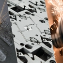
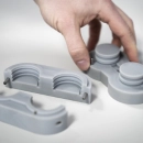
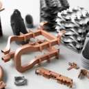
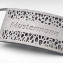
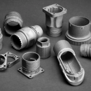
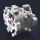
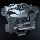
In tool making, 3D printing is mainly used for injection molding tool inserts with conformal cooling: the cooling channels follow the contour of the part instead of being drilled in straight lines. This ensures more uniform heat dissipation, shorter cycle times and less warpage. In addition, there are lightweight components, rapid tooling inserts for prototypes and small series, as well as fixtures and gauges.
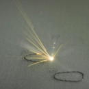
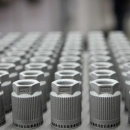
Tool inserts are produced by selective laser melting (SLM), for example from tool steel 1.2709. On the PROTIQ Marketplace, you will find more than 160 materials and more than 12 processes from more than 40 suppliers – and, with CNC machining, the right post-processing too.
Conformal cooling
What are the benefits of conformal cooling in an injection mold?
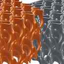
In injection molding, cooling often determines the cycle time. Conventionally, cooling channels are drilled and therefore run in straight lines – with complex geometries, they can hardly be routed evenly and close to the surface. In 3D printing, the channels are created directly in the part and follow its contour.
The result: heat is dissipated more evenly, and molded parts cool faster and more uniformly. This shortens the cycle time, reduces warpage and rejects and improves the quality of the injection-molded parts. Over the service life of a tool, this lowers the unit price of the series product.
↑ Back to overview
Drilled cooling or conformal cooling?
| Conventionally drilled | 3D-printed, conformal | |
|---|---|---|
| Cooling channels | Drilled in straight lines, only limited combinations | Freely follow the contour of the part |
| Distance to the surface | Uneven, often too far away | Uniform and close to the surface |
| Heat dissipation | Uneven, hotspots possible | More uniform, homogeneous surface temperature |
| Cycle time | Longer, cooling determines the cycle | Significantly shorter possible |
| Part quality | Warpage due to uneven cooling | Less warpage, more consistent quality |
Applications
What can be 3D printed in tool making?
In addition to tool inserts with conformal cooling, parts with complex geometries, short-term demand or small quantities in particular benefit from 3D printing.
Tool inserts
Mold inserts and cores for injection molding and forming tools with conformal cooling channels, made from tool steel.
Lightweight components
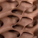
Plates and structural parts with internal ribs or lattice structures – lighter with high stiffness.
Rapid tooling
Tool inserts for injection molding or vacuum casting of prototypes and small series – fast and directly from 3D data. More about rapid tooling
Fixtures and gauges
Clamping and holding fixtures, gauges, grippers and adapters – often made of resilient plastic by laser sintering.

Function before manufacturability
Because complex internal shapes can hardly be produced with machining or forming processes, potential often remains untapped in conventional tool making. In 3D printing, the part is built up layer by layer directly from the CAD data – the geometry can be fully oriented towards function and design.
This enables not only conformal cooling channels, but also lighter tool components, integrated functions and new design approaches.
↑ Back to overviewMaterials
Which materials are suitable for 3D-printed tools?
Tool inserts are mainly made from tool steels by selective laser melting (SLM). According to the PROTIQ datasheet, maraging tool steel 1.2709 reaches 53 ± 2 HRC and a tensile strength of 2,030 ± 70 MPa after heat treatment.
| Material | Type | Tensile strength | Hardness |
|---|---|---|---|
| Tool steel 1.2709 (MS1) | Maraging tool steel | 1,100 ± 100 MPa (as built) 2,030 ± 70 MPa (heat-treated) |
33–37 HRC (as built) 53 ± 2 HRC (heat-treated) |
| Stainless steel CX | Stainless tool steel | 1,080 MPa (as built) 1,730 ± 10 MPa (heat-treated) |
50 HRC (heat-treated) |
Values according to PROTIQ material datasheets; click on the material to open the datasheet (1.2709 datasheet available in German).
Further materials – including plastics for fixtures and gauges – can be found in the configurator. An overview is available on the page Steel in 3D printing.
↑ Back to overviewDesign
What should be considered in the design?
The basis is a printable CAD model of the workpiece. To achieve the surface quality required for injection molds, all external surfaces should be given a machining allowance of 0.7 to 1 mm. After printing, the parts are conventionally finished and machined to size.
- Plan a machining allowance: 0.7 to 1 mm on all external surfaces for machining.
- Route cooling channels conformally: uniform distance to the mold surface for homogeneous temperature control.
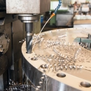
- Consider post-processing: fits, parting lines and functional surfaces are brought to size by CNC machining.
- Take heat treatment into account: hardness and strength are set by heat treatment after printing.
Further information on creating data can be found under How to create a 3D file.
↑ Back to overview
Ordering
Ordering tooling components on the PROTIQ Marketplace
Upload your CAD model in the configurator, choose material and quantity and compare the offers with price and delivery time. Production starts directly after the order is received – you usually receive your part a few days after placing the order.
- Upload your CAD modelUpload your model in the configurator – with machining allowance on the external surfaces.
- Choose the materialFor example tool steel 1.2709 by selective laser melting.
- Compare offersYou see price and delivery time and decide for yourself where to order.
- Post-processFunctional surfaces are machined to size – you will also find CNC machining on the Marketplace.
For complex tooling projects, start a project inquiry or write to our expert.
↑ Back to overview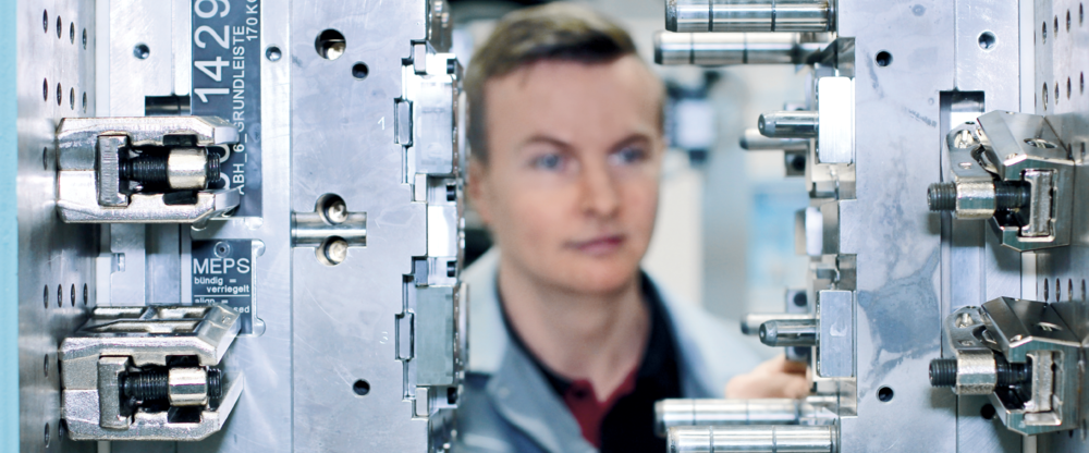
Experience
Our roots: the Tooling Shop of the Year
PROTIQ is a subsidiary of Phoenix Contact and emerged from its internal tooling shop.
This tooling shop looks back on more than 50 years of experience and has twice been named overall winner and “Tooling Shop of the Year” in the “Excellence in Production” competition. An understanding of the requirements of tool making still shapes PROTIQ today.
↑ Back to overviewFAQ
Frequently asked questions about 3D printing in tool making
Why is 3D printing suitable for tool making?
Because tool inserts with conformal cooling channels, lightweight structures and integrated functions can be produced directly from CAD data – geometries that can hardly be drilled or milled. Added to this are short delivery times and cost-effectiveness for one-offs.
What is conformal cooling?
With conformal cooling, the cooling channels of a tool insert follow the contour of the molded part instead of being drilled in straight lines. This ensures more uniform heat dissipation, shorter cycle times and less warpage.
Which parts can be 3D printed in tool making?
Tool inserts and cores, lightweight components, rapid tooling inserts for prototypes and small series, clamping and holding fixtures, gauges, grippers, adapters and spare parts.
What machining allowance does a 3D-printed tool insert need?
To achieve the required surface quality, all external surfaces should be designed with a machining allowance of 0.7 to 1 mm. After printing, they are conventionally finished and machined to size.
What is rapid tooling?
Rapid tooling refers to the fast production of tools or tool inserts directly from 3D CAD data – for example for injection molding or vacuum casting of prototypes and small series.
How quickly will I receive a tooling component from 3D printing?
Production starts directly after the order is received. You usually receive your part a few days after placing the order; the exact delivery time is shown in the offer comparison.
When is 3D printing worthwhile in tool making?
Especially for tools whose cycle time benefits from better cooling, for complex geometries, for one-offs and small series, and for short-term demand.
↑ Back to overview