

 Deutsch
 English
 Italiano




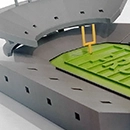
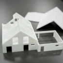

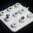

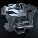

Binder Jetting: Powder Bed 3D Printing without Support Structures
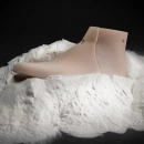
Binder jetting is a powder bed 3D printing process: a recoater applies a thin layer of powder, and a print head wets the areas where the part is created with a liquid binder, bonding the powder particles. The part is built layer by layer. Because the surrounding loose powder supports the part, no support structures are needed.
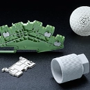
Depending on the machine, binder jetting is used for plastics, metals, sand or ceramics. On the PROTIQ Marketplace, the process is currently offered with PMMA-based plastics – for example for architectural and trade fair models, inspection gauges, fixtures and prototypes. You upload your 3D data, choose the material and usually see the price and production time right away.
Binder jetting at a glance
- Process principle
- Powder bed, powder particles are bonded with a liquid binder
- Materials
- currently PMMA-based plastics
- Support structures
- none – the powder bed supports the part
- Resolution in build direction
- 0.125–0.15 mm depending on material
- Surface
- slightly rough, due to the powder
- Quantity
- Single part to small batch
Guide values, not guaranteed properties. The information provided by the supplier in the ordering process or in the quote is authoritative.
How it works
How does binder jetting work?
A recoater spreads a thin layer of powder on the build platform. A print head moves over it and applies a liquid binder exactly where the cross-section of the part lies – the powder particles bond. The platform then lowers by one layer thickness, and the process repeats until the last layer. Finally, the part is removed from the powder bed and freed from loose powder.
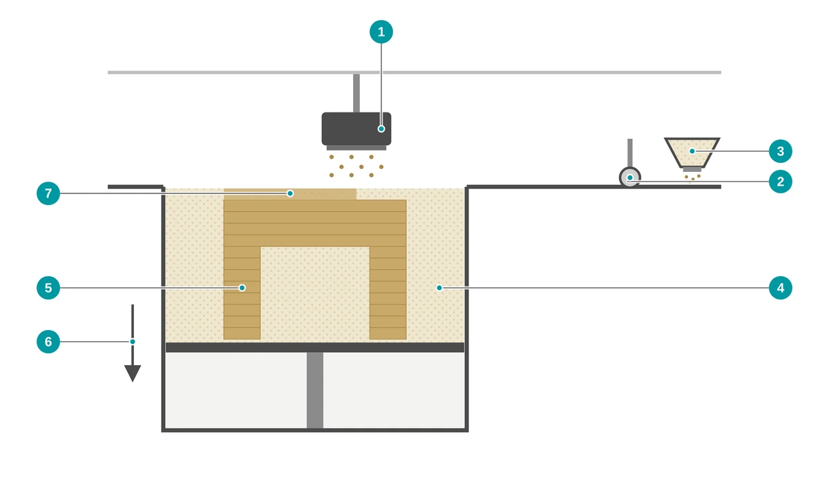
- 1 Print head applies the liquid binder
- 2 Recoater spreads a new layer of powder
- 3 Powder supply
- 4 Powder bed – loose powder supports the part
- 5 Part, bonded layer by layer
- 6 Build platform lowers after each layer
- 7 Binder bonds the powder particles of the current layer
- Prepare data The 3D model is placed in the build space and sliced into layers. No support structures are needed.
- Apply powder The recoater spreads a thin, even layer of powder.
- Print binder The print head wets the cross-section with binder and bonds the powder particles. The platform then lowers.
- Curing Depending on the material system, the part continues to cure after printing before it is removed.
- Depowdering The part is removed from the powder bed and freed from loose powder – for example with a brush and compressed air.
- Finishing Whether further finishing steps are possible depends on the supplier – you can see the available options in the configurator.


Binder jetting or SLS?
What is the difference between binder jetting and laser sintering?
Both processes work in a powder bed and require no support structures. In laser sintering, a laser melts the powder particles; in binder jetting, a liquid binder bonds them. Binder jetting is particularly suitable for models, gauges and prototypes, laser sintering for mechanically loaded functional parts.
| Binder jetting | Laser sintering (SLS) | |
|---|---|---|
| Bonding of the powder particles | Binder bonds the particles | Laser melts the particles |
| Support structures | none | none |
| Materials on the Marketplace | PMMA-based plastics | including polyamides, also flame-retardant or electrically dissipative |
| Surface | slightly rough | slightly rough and matte |
| Typical use | Models, gauges, fixtures, prototypes | load-bearing functional parts |
Which process suits your part better depends on the intended use, load, size and quantity. Upload your file and compare the offers directly in the configurator.
↑ Back to overviewAdvantages
What are the advantages of binder jetting?
Binder jetting produces parts in a powder bed without support structures. With the PMMA-based materials, it is particularly suitable for models, gauges and prototypes.
No support structures
The loose powder supports the part. Overhangs and undercuts are possible without supports – internal structures too, provided the loose powder can be removed through openings.
Great design freedom
Complex geometries and several parts can be produced in one build process.
Easy to machine
AE21 and AE12+ are easy to machine – for example for drilling, milling or reworking mating surfaces.
Translucent option
AE21 is greenish translucent – for example for translucent housings.
Made for models
AE12+ is matte white – for architectural, art and trade fair models.
No tooling, from a single part
No tooling, no mold costs – from single parts to small batches.
Materials
Which materials are available for binder jetting?
On the PROTIQ Marketplace, binder jetting is currently offered with PMMA-based materials: the greenish translucent AE21 and the matte white AE12+.
You can see which materials are currently available in the configurator after uploading – where you will also find the suppliers’ datasheets.
AE21 – greenish translucent
PMMA-based material with a wide range of applications, especially in mold making – for example for inspection gauges, fixture construction, prototypes and translucent housings.
AE12+ – matte white
PMMA-based material, mainly for model making – for example for architectural, art and trade fair models.
Material data compared
| Material | Color | Tensile strength (MPa) | Elongation (%) | Young’s modulus (MPa) | Flexural strength (MPa) | Heat deflection temperature HDT-A 1.8 MPa (°C) | Residual porosity (%) |
|---|---|---|---|---|---|---|---|
| AE21 | greenish translucent | 38 | 1.9 | 2,460 | 52 | 56 | < 2 |
| AE12+ | matte white | 20 / 10¹ | 3 / 2¹ | 1,200 | 25 / 15¹ | 56 | < 15 |
Values from the datasheets on the PROTIQ Marketplace (as of 07/2022 and 02/2021 respectively). The datasheets state them as guide values from individual measurements; they do not constitute guaranteed properties. Flexural strength was determined according to DIN EN ISO 178 for AE21 and according to a factory standard for AE12+ and is therefore only comparable to a limited extent. The heat deflection temperature is not a continuous service temperature. The supplier’s information is authoritative.
¹ Two values each, one of them in build direction – the properties of AE12+ depend on direction.
Technical data
Technical data and design guidelines
The resolution in build direction is 0.125 mm (AE21) or 0.15 mm (AE12+), and the dimensional accuracy is 0.7 mm plus less than 0.5 % of the longest axis. The maximum part size depends on the machine.
| Feature | Value |
|---|---|
| Maximum part size | depending on the supplier’s machine; when you upload, the system automatically checks whether the part fits into the build space |
| Resolution in build direction | 0.125 mm (AE21) or 0.15 mm (AE12+) |
| Dimensional accuracy | 0.7 mm + < 0.5 % of the longest axis |
| Support structures | none |
| Surface | slightly rough, due to the powder |
| Post-processing | easy to machine |
Guide values, not guaranteed properties. The information provided by the supplier in the ordering process or in the quote is authoritative.
What to consider when designing
- The powder must come out Cavities need openings so that loose powder can be removed after printing. Completely closed cavities remain filled with powder.
- Fine structures Very thin webs and small details can be damaged during depowdering. It is better to plan in some reserve.
- Choose the material according to purpose AE21 has the higher tensile strength and the lower residual porosity, while AE12+ is intended for models with a matte white surface.
- Consider directional dependence For AE12+, there are two values each for tensile and flexural strength, one of them in build direction. If your part is subject to mechanical loads, please contact us before ordering.
- Plan for rework Mating surfaces and holes are easy to machine afterwards. Plan some allowance for this.
- Test under real conditions Test gauges and fixtures under realistic conditions before you use them.
Limits & alternatives
When is another process the better choice?
- Mechanical load The tensile strength is 38 MPa (AE21) or 20 and 10 MPa (AE12+), the elongation 1.9 % or 3 and 2 %. For tough, heavily loaded functional parts, laser sintering or Multi Jet Fusion may be better suited.
- Surface and details The surface is slightly rough due to the powder; the resolution in build direction is 0.125 mm (AE21) or 0.15 mm (AE12+). For smooth surfaces and fine details, stereolithography is suitable.
- Temperature The heat deflection temperature (HDT-A) is 56 °C. For use at higher temperatures, other materials are an option.
- Residual porosity The residual porosity is below 2 % (AE21) or below 15 % (AE12+). If parts need to be gas-tight or liquid-tight, please clarify suitability with us in advance.
| Process | Strengths | May be the better choice if … |
|---|---|---|
| Laser sintering (SLS) | Load-bearing, tough functional parts without support structures | … your part is subject to mechanical loads |
| Multi Jet Fusion (MJF) | Powder bed process for functional parts, also in full color | … you need load-bearing functional parts or colored parts |
| Stereolithography (SLA) | Smooth surfaces and fine details, depending on the resin also transparent | … your model needs a smooth surface or fine details |
| Fused Deposition Modeling (FDM) | Parts made of thermoplastics, built up layer by layer from a filament | … you need parts made of a thermoplastic |
Multi Jet Fusion, FDM and Fused Deposition Modeling are trademarks of their respective owners. AE21 and AE12+ are material designations of their manufacturer.
↑ Back to overviewApplications
What is binder jetting used for?
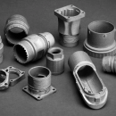
With the PMMA-based materials, architectural, art and trade fair models, design studies, prototypes, inspection gauges, fixtures and translucent housings are produced.

Architecture
Architectural and trade fair models with a matte white surface, for example made of AE12+.
About architecture
Prototyping
Prototypes, inspection gauges and fixtures – for example made of AE21, also translucent.
About prototypingOrdering
How do I order binder jetting parts?
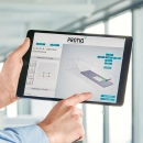
Upload your 3D file, choose material and process and see the available offers.
- Upload file Upload your 3D data in the configurator. The system automatically checks whether the part fits into the build space.
- Choose material Choose from more than 160 materials and more than 12 processes – for example AE12+ with binder jetting.
- Check the offer As a rule, you immediately see the price and production time of the available suppliers.
- Order You order directly online at the selected price.
FAQ
Frequently asked questions about binder jetting
What is binder jetting?
Binder jetting is a powder bed 3D printing process. A print head applies a liquid binder to a thin layer of powder and bonds the powder particles where the part is created. This is how the part grows layer by layer – without support structures.
What is the difference between binder jetting and SLS?
Both work in a powder bed without support structures. In laser sintering, a laser melts the powder particles; in binder jetting, a binder bonds them. Laser-sintered polyamide parts are generally tougher and can withstand higher mechanical loads; the properties of the respective material are decisive.
Which materials are available for binder jetting?
The PROTIQ Marketplace currently offers the PMMA-based materials AE21 (greenish translucent) and AE12+ (matte white). Depending on the machine, binder jetting is also used for metals, sand or ceramics in general.
What are AE21 and AE12+ suitable for?
AE21 is suitable, for example, for inspection gauges, fixture construction, prototypes and translucent housings. AE12+ is intended for architectural, art and trade fair models.
How accurate is binder jetting?
For AE21 and AE12+, the dimensional accuracy is 0.7 mm plus less than 0.5 % of the longest axis, and the resolution in build direction is 0.125 mm or 0.15 mm. The supplier’s information is authoritative.
Can binder jetting parts be post-processed?
Yes. AE21 and AE12+ are easy to machine. Holes and mating surfaces can be reworked; further finishing steps depend on the offer.
How large can the parts be?
That depends on the supplier’s machine. When you upload, the system automatically checks whether your part fits into the build space. If it is too large, please contact us.
How much does a binder jetting part cost?
The price depends on factors such as part volume, size, material and quantity. After uploading your file, you will usually see the suppliers’ prices immediately in the configurator.