


 Deutsch
 English
 Italiano
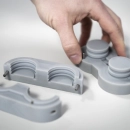
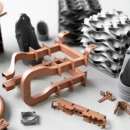
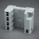
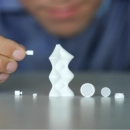
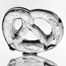

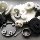
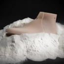


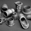
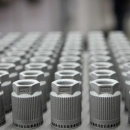
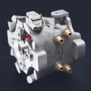





Material Jetting (PolyJet / MultiJet Modeling): 3D printing droplet by droplet
Material jetting (MJT according to DIN EN ISO/ASTM 52900) is a 3D printing process in which a print head selectively deposits fine droplets of material, layer by layer. Well-known manufacturer-specific variants are PolyJet (Stratasys) and MultiJet Printing or MultiJet Modeling (3D Systems). On common machines, the material is a liquid photopolymer that is cured with UV light. Overhangs are supported by a separately deposited support material that is removed after printing.
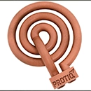
Depending on the machine and material, material jetting can produce rigid, transparent, multicolor or elastic parts. On the PROTIQ Marketplace, the process is currently offered for elastic parts made of silicone-like printing material – for example for prototypes of seals, grommets or grips. The parts are produced on a material jetting machine that is not sold under the names PolyJet or MultiJet. You upload your 3D data, select the material and see the price and production time.
Material jetting at a glance
- Process principle
- Material jetting
- Materials on the Marketplace
- currently elastic, silicone-like printing materials, Shore A 35 and A 65
- Layer thickness
- 30 µm
- Surface
- comparatively smooth due to the process
- Quantity
- single part to small batch
Information on materials, support material and layer thickness taken from the supplier’s data sheet on the PROTIQ Marketplace; not guaranteed properties. The information provided by the respective supplier in the ordering process is binding.
How it works
How does material jetting work?
On common photopolymer machines, a print unit moves across the build platform – similar to an inkjet printer – and deposits fine droplets of part and support material wherever the cross-section requires them. UV lamps, usually mounted on the print unit, cure the droplets right after deposition. The distance between print head and part is then increased by one layer thickness, usually by lowering the platform.
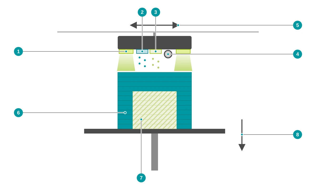
- 1 UV lamps cure the deposited droplets immediately
- 2 Print head for the part material – many fine nozzles
- 3 Print head for the support material
- 4 Roller levels the freshly deposited layer
- 5 The print unit moves across the build area
- 6 Part, built up layer by layer
- 7 Support material – removed after printing
- 8 Build platform lowers after each layer
- Data preparation The 3D model is oriented and sliced into thin layers. The software determines where support material is needed.
- Depositing droplets The print heads deposit part and support material in fine droplets – along the cross-section of the current layer.
- Curing with UV light UV lamps cure the material right after it has been deposited.
- Leveling and lowering On many machines, a roller levels the layer. The build platform then lowers by one layer thickness, and the cycle repeats.
- Removing support material After printing, the support material is removed – depending on the system, for example dissolved in water or a solution, removed with a water jet or melted out.
- Cleaning and inspection The part is cleaned, dried and inspected.
Material jetting on video
The video shows the operating principle of material jetting.
Because a separate support material is printed as well, undercuts and internal structures are possible – as long as the support material can be removed afterwards.
↑ Back to overviewSilicone-like or TPU?
Which process is suitable for elastic parts?
There are several ways to produce elastic parts: material jetting with silicone-like printing material, TPU in the powder bed, or vacuum casting with PU casting resins, which can also be elastic depending on the resin. Material jetting stands out for fine details, TPU from the powder bed needs no support structures, and vacuum casting is a good option for several identical parts.
| Material jetting (silicone-like) | TPU in the powder bed (MJF, SLS) | Vacuum casting | |
|---|---|---|---|
| Material | silicone-like printing material | TPU (thermoplastic polyurethane) | PU casting resins |
| Hardness | Shore A 35 or A 65 (according to the data sheet) | depending on the material, according to the data sheet | depending on the casting resin |
| Surface | comparatively smooth, fine details | slightly rough and matte | depends on the master pattern |
| Supports / tooling | support material, removed after printing | no support structures, no tooling | silicone mold made from a master pattern |
| Typical use | soft prototypes with fine details, single parts | elastic functional parts such as dampers, cushions or grips | small batches of identical parts |
Which process suits your part depends on hardness, load, geometry and quantity. For the 3D printing processes, you will see the offers directly in the configurator after uploading your file. For more on this topic, see 3D-printed seals.
↑ Back to overviewAdvantages
What are the advantages of material jetting?
Material jetting reproduces fine details and requires no tooling. With the silicone-like printing material currently on offer, it is a good choice for soft parts – from the first design sample to functional testing.
Elastic, printed directly
Soft parts are produced directly from the 3D data without a mold – with Shore A 35 or A 65 according to the data sheet.
Fine details, thin walls
With a layer thickness of 30 µm, fine structures can be reproduced; according to the data sheet, the minimum wall thickness is 0.3 or 0.5 mm.
Smooth surface
Due to the process, the surface is usually comparatively smooth; surfaces in contact with the support material may be more matte.
Water-soluble support material
According to the data sheet, the support material is water-soluble. This protects thin-walled, elastic parts during removal.
Heat-resistant according to the data sheet
According to the supplier’s data sheet, heat-resistant up to 150 °C (Shore A 65) or 200 °C (Shore A 35) – without information on duration and load.
No tooling costs, from a single part
No tooling, no mold costs – well suited for testing soft parts early, before series tooling is made.
Materials
Which materials are available for material jetting?
The machines described here process liquid photopolymers. On the PROTIQ Marketplace, there are currently two elastic, silicone-like printing materials of different hardness: AR-G1L (Shore A 35) and AR-G1H (Shore A 65).
You can see which materials are currently available in the configurator after uploading your file – where you will also find the suppliers’ valid data sheets. What Shore hardness tells you is explained in our article Correctly interpreting Shore hardness values.
Soft: AR-G1L
Silicone-like printing material with Shore A 35 – for very soft, flexible parts such as seal samples, buffers or soft-touch elements.
Firmer: AR-G1H
Silicone-like printing material with Shore A 65 – more dimensionally stable and with higher tensile strength, for example for grommets, cable guides or grips.
Properties compared
| Material | Shore hardness A | Tensile strength (MPa) | Elongation at break (%) | Density (g/cm³) | Water absorption (%) | Heat-resistant up to (°C)¹ |
|---|---|---|---|---|---|---|
| AR-G1L | 35 | 0.5–0.8 | 160 | 1.03 | < 0.4 | 200 |
| AR-G1H | 65 | 2.0–2.5 | 160 | 1.03 | < 0.4 | 150 |
Values taken from the supplier’s data sheet on the PROTIQ Marketplace; tested according to ASTM D412 (tensile strength, elongation at break), D2240 (Shore hardness) and D792 (density). Not guaranteed properties; the values may depend on part geometry and build orientation, among other things. The data sheet of the respective supplier in the ordering process is binding.
¹ Supplier information without details on duration and load; not a guaranteed continuous service temperature. Whether a part withstands the operating conditions must be checked on a case-by-case basis.
Technical data
Technical data and design guidelines
According to the supplier’s data sheet, the silicone-like printing materials are printed with a layer thickness of 30 µm; the minimum wall thickness is 0.5 mm (AR-G1L) or 0.3 mm (AR-G1H). The data sheet does not state tolerances. When you upload your file, the system automatically checks whether your part fits into the build space.
| Feature | Value |
|---|---|
| Maximum part size | depends on the supplier’s machine – checked automatically on upload |
| Layer thickness | 30 µm (according to the supplier’s data sheet) |
| Minimum wall thickness | 0.5 mm (AR-G1L) or 0.3 mm (AR-G1H), according to the supplier’s data sheet |
| Tolerances | not stated in the data sheet; please inquire in advance if needed |
| Support material | water-soluble according to the supplier’s data sheet |
| Hardness | Shore A 35 (AR-G1L) or Shore A 65 (AR-G1H) |
| Surface | comparatively smooth due to the process (not specified in the data sheet) |
Guide values, not guaranteed properties. The information provided by the respective supplier in the ordering process or in the quote is binding.
What to consider when designing
- Observe the minimum wall thickness Do not design walls thinner than stated in the data sheet – with very soft material, it is better to allow some reserve.
- The support material must come out Cavities and channels need openings so that the support material can be removed completely after printing. Fully enclosed cavities are filled with support material that cannot be removed afterwards.
- Choose the hardness to suit the function Shore A 35 is very soft and yields easily, Shore A 65 is more dimensionally stable and resilient. For seals, the choice depends on contact pressure and gap size.
- Support fine, soft structures Thin, long lips or webs made of soft material can deform. Reinforce them where the function allows.
- Allow for compression For seals and fits, take compression into account in the design. If needed, inquire about tolerances in advance.
- Test under real conditions Printed material does not behave like a series material in every respect. Therefore, test prototypes under realistic conditions.
Limits & alternatives
When is another process the better choice?
- Mechanical load According to the data sheet, the tensile strength is 0.5–2.5 MPa. Check whether this is sufficient for your application; for mechanically loaded functional parts, TPU from the powder bed or cast elastomers are also options.
- Quantity The process is intended for single parts and small quantities. For small batches, vacuum casting may be more economical, and for large quantities, injection molding.
- Support material The support material must be completely removable. This limits cavities and very narrow channels.
- Approvals The data sheet contains no information on food contact or biocompatibility. For such applications, suitability must be clarified with the supplier in advance.
| Process | Strengths | May be the better choice if … |
|---|---|---|
| Multi Jet Fusion (MJF) with TPU | Elastic functional parts made of TPU without support structures | … you need an elastic functional part without support material |
| Laser sintering (SLS) | Robust parts without support structures, depending on the supplier also made of TPU | … your part needs to be robust |
| Stereolithography (SLA) | Smooth, rigid parts, transparent depending on the material | … your part should be rigid rather than elastic |
| Vacuum casting | Small batches made of PU casting resins, also elastic – often with a 3D-printed master pattern | … you need several identical parts in small quantities |
| Injection molding | Economical for large quantities | … the quantity is large enough to justify a mold |
PolyJet, MultiJet and Multi Jet Fusion are trademarks or designations of their respective owners. They are mentioned solely to describe the processes.
↑ Back to overviewApplications
What is material jetting used for?
Depending on the material, material jetting is used to produce design and visual models, prototypes and single parts. With the silicone-like printing material currently on offer, soft prototypes and single parts are produced: seal samples, buffers, grommets, cable guides, grips and soft-touch elements or soft visual models.

Seals
Seal samples and custom seals in small quantities – without tooling and quickly adapted.
To seals
Prototyping
Test soft components such as grips, buttons or grommets early – also together with rigid prototypes.
To prototyping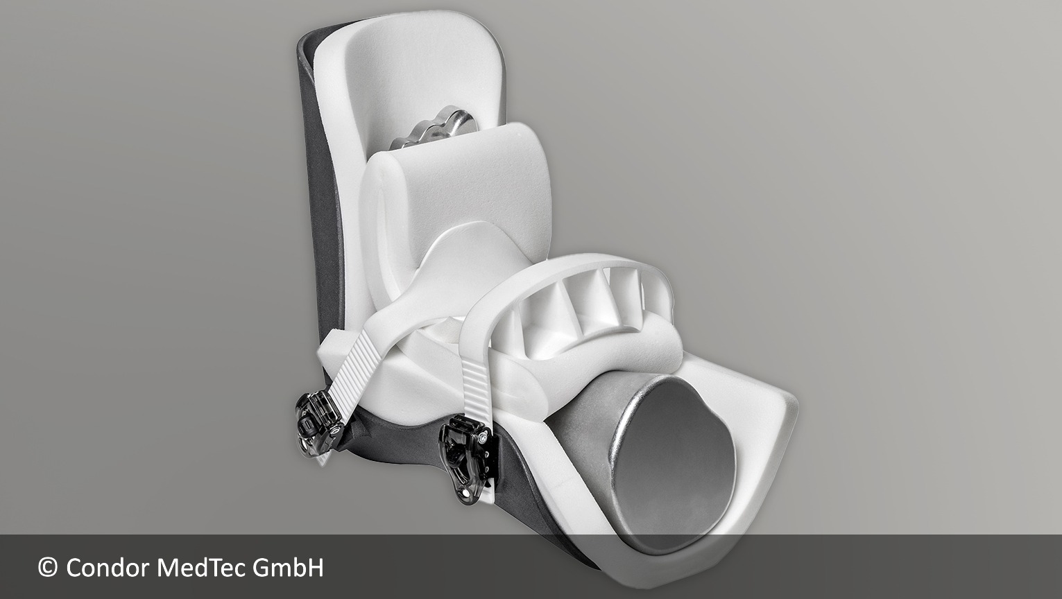
Medical technology
Soft visual models and prototypes. The data sheet contains no information on biocompatibility; suitability for medical applications must be clarified on a case-by-case basis.
To medical technologyOrdering
How do I order material jetting parts?
Upload your 3D file, select material and process and view the available offers.
- Upload your file Upload your 3D data in the configurator. The system automatically checks whether the part fits into the build space.
- Select the material Choose from over 160 materials and over 12 processes – for example AR-G1L with Shore A 35.
- Check the offer As a rule, you immediately see the price and production time of the suppliers who can manufacture your part.
- Order You order online at the selected price.
FAQ
Frequently asked questions about material jetting, PolyJet and MultiJet
What is PolyJet or MultiJet Modeling?
PolyJet and MultiJet are manufacturer-specific variants of material jetting. A print head deposits fine droplets of material layer by layer – on common machines a liquid photopolymer that is cured with UV light. Overhangs are supported by a support material that is removed after printing.
What is the difference between PolyJet and MultiJet?
PolyJet is a designation used by Stratasys, MultiJet Printing (formerly MultiJet Modeling) one used by 3D Systems. Both belong to material jetting. They differ in machines, materials and the type of support material, among other things.
Can silicone be 3D printed?
There are UV-curing printing materials that the manufacturer calls silicone printing material – we refer to them as silicone-like printing material. On the PROTIQ Marketplace, these are currently AR-G1L and AR-G1H with a Shore hardness of A 35 and A 65 according to the data sheet. Their properties do not correspond in every respect to those of cast or injection-molded silicone.
How soft are parts made of silicone-like printing material?
According to the data sheet, AR-G1L has a Shore hardness of A 35 and is very soft. AR-G1H has Shore A 65 and is more dimensionally stable. According to the data sheet, both reach an elongation at break of 160%.
How heat-resistant is the silicone-like printing material?
According to the supplier’s data sheet, AR-G1H is heat-resistant up to 150 °C and AR-G1L up to 200 °C. The data sheet gives no information on duration and load; whether a part withstands the operating conditions must be checked on a case-by-case basis.
Silicone-like material or TPU – which is the better fit?
Silicone-like printing material from material jetting offers fine details, for example for soft prototypes. TPU from the powder bed (MJF or SLS) needs no support structures and is used for elastic functional parts such as dampers, cushions or grips. Which solution fits depends on hardness, load and geometry.
How accurate is the process?
According to the supplier’s data sheet, the layer thickness is 30 µm. It describes the resolution in the build direction, not the dimensional accuracy. The data sheet does not state tolerances; please inquire about them in advance if needed.
How large can the parts be?
That depends on the supplier’s machine. When you upload your file, the system automatically checks whether your part fits into the build space. If it is too large, please contact us.
How much does a part made of silicone-like printing material cost?
The price depends mainly on part volume, size, material and quantity. After uploading your file, you will usually see the suppliers’ prices in the configurator right away.