


 Deutsch
 English
 Italiano

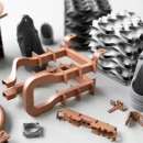
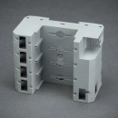
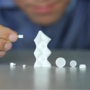
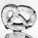









CLIP Process (Digital Light Synthesis): 3D Printing of Robust and Elastic Resin Parts
Continuous Liquid Interface Production (CLIP) is a 3D printing technology developed by the US company Carbon; Carbon calls the overall process based on it Digital Light Synthesis (DLS). A projector exposes liquid resin from below through a window that is permeable to light and oxygen, while the build platform continuously pulls the part upward. Many CLIP resins are additionally post-cured in an oven after printing and only then reach their final properties.
The process belongs to vat photopolymerization – like stereolithography. Typical fields of application are functional parts, housings, brackets and clips, elastic dampers and lattice structures, as well as small batches. On the PROTIQ Marketplace, CLIP is currently offered with a wide range of resins: you upload your 3D data, choose the material and usually see the price and production time right away.
CLIP at a glance
- Process principle
- Vat photopolymerization with continuous exposure from below
- Materials
- Epoxy-, polyurethane- and methacrylate-based resins as well as elastomers
- Post-processing
- Cleaning; depending on the resin, post-curing in an oven or with UV light
- Support structures
- required
- Surface
- comparatively smooth
- Quantity
- Single part to small batch
Guide values, not guaranteed properties. The information provided by the supplier in the ordering process or in the quote is authoritative.
How it works
How does the CLIP process work?
A projector below the resin vat beams a sequence of UV images – the cross-sections of the part – through a transparent window into the resin. Because the window is permeable to oxygen, a thin layer of resin directly above it remains liquid: the so-called dead zone. Above it, the resin cures while the platform continuously pulls the part upward and fresh resin flows in. Because the resin does not stick to the window, the part does not have to be detached from the vat bottom after each layer – so it can grow continuously.
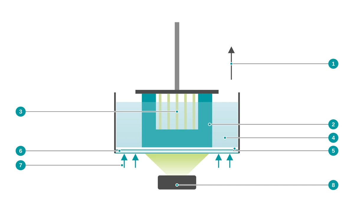
- 1 Build platform continuously pulls the part upward
- 2 Part – built upside down on the platform
- 3 Support structures – removed after printing
- 4 Liquid resin in the vat
- 5 “Dead zone”: thin layer of resin that does not cure
- 6 Window permeable to light and oxygen
- 7 Oxygen inhibits curing directly at the window
- 8 Projector exposes the cross-section as a UV image
- Prepare data The 3D model is oriented and provided with support structures. The software uses it to generate the image sequence for the projector.
- Continuous exposure The projector exposes the cross-sections one after the other while the platform continuously pulls the part out of the resin.
- Cleaning Adhering resin is cleaned off the part – depending on the resin, with a solvent such as isopropanol.
- Remove supports The support structures are removed – before or after post-curing, depending on the resin; small marks may remain at the contact points.
- Post-curing If the resin requires it, the part is post-cured in an oven or under UV light. Only then does it reach the properties stated in the datasheet.
- Inspection and finishing The part is inspected. Depending on the offer, further processing steps are possible, such as painting.
CLIP or SLA?
What is the difference between CLIP and stereolithography?
Both processes cure liquid resin with light. In stereolithography, a laser usually traces each cross-section layer by layer. In the CLIP process, a projector projects entire cross-sections; thanks to the dead zone, the part does not have to be detached from the vat bottom after each layer and grows continuously. Many CLIP resins only reach their final properties through thermal post-curing.
| CLIP / DLS | Stereolithography (SLA) | |
|---|---|---|
| Exposure | Projector, entire cross-section as an image, from below | usually a laser that traces the cross-section |
| Build-up | continuous, platform moves steadily upward | layer by layer |
| Resins | including dual-cure resins with thermal post-curing, also elastomers | robust, transparent and temperature-resistant resins |
| Post-curing | depending on the resin, in an oven or with UV light | with UV light, sometimes additionally thermal |
| Support structures | required | required |
| Typical use | Functional parts, elastic lattice structures, small batches | Design and functional prototypes, highly transparent parts, master models |
Which process suits your part better depends on material, load, geometry and quantity. Upload your file and compare the offers directly in the configurator.
↑ Back to overviewAdvantages
What are the advantages of the CLIP process?
The CLIP process combines smooth surfaces with resins for technical use – from stiff and temperature-resistant to tough and elastic.
Smooth surfaces
Compared to powder bed or extrusion processes, CLIP parts usually have a smooth surface.
Engineering materials
Dual-cure resins reach their final properties after post-curing in an oven – EPX 82, for example, has a heat deflection temperature of 120 °C at 1.82 MPa according to the datasheet.
Elastomers and lattice structures
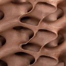
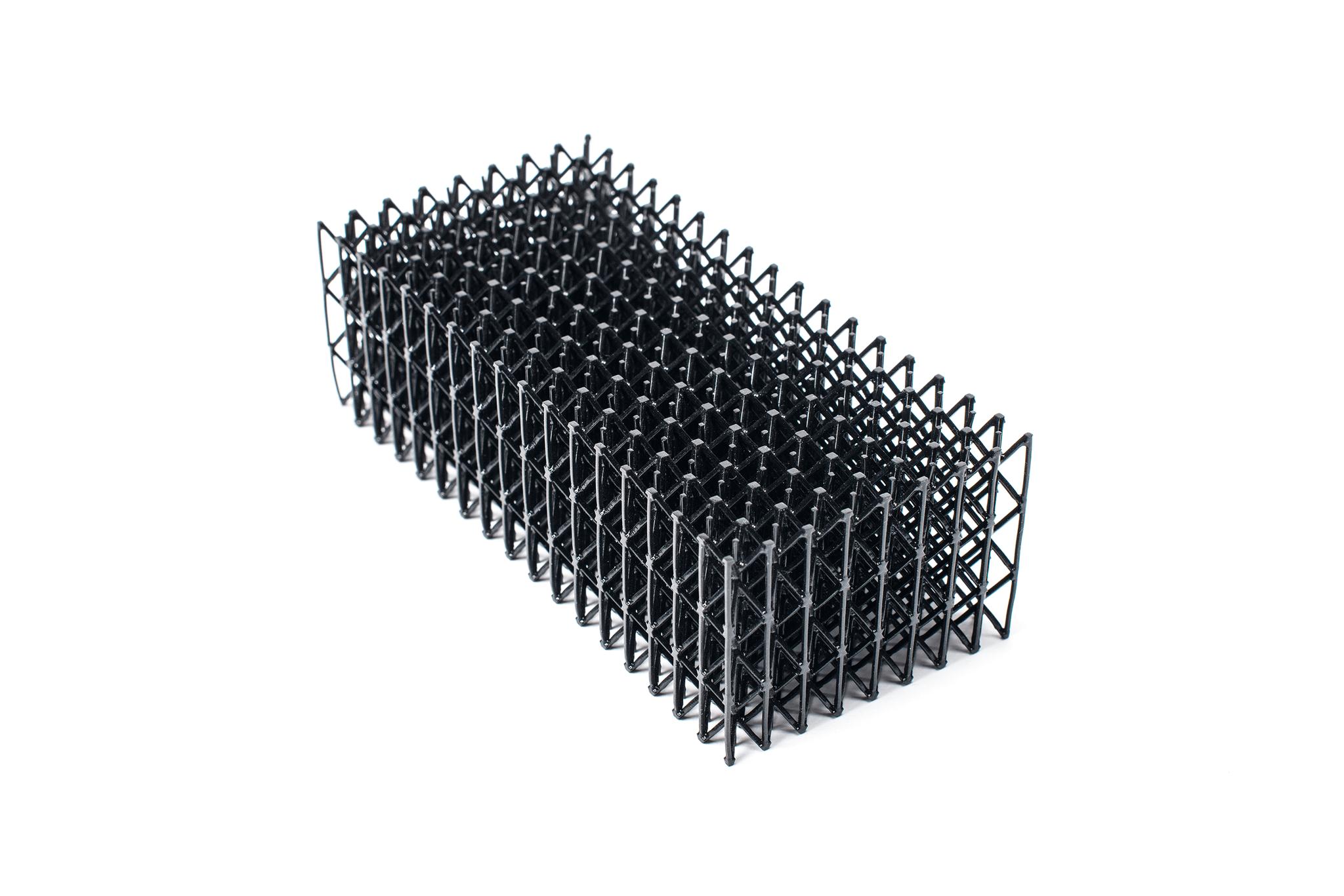
Elastomers such as EPU 40, EPU 41 or SIL 30 produce soft parts; according to the manufacturer, EPU 41 is particularly suitable for elastic lattice structures.
Flame-retardant options
According to the datasheet, EPX 86FR achieves UL 94 V-0 at 2.0 mm and V-1 at 1.5 mm specimen thickness. The rating applies to standardized test specimens, not to the finished part.
Less direction-dependent
According to Carbon, parts made from the dual-cure resins show higher isotropy than parts from other additive manufacturing processes. Depending on the build direction, the values may still vary.
No tooling, from a single part
No tooling, no mold costs – from single parts to small batches.
Materials
Which materials are available for the CLIP process?
The CLIP process uses liquid resins – from stiff epoxy resins and tough polyurethane resins to elastomers. On the PROTIQ Marketplace, the current choice includes EPX 82, EPX 86FR, RPU 70, RPU 130, MPU 100, FPU 50, UMA 90, Loctite 3D IND405, EPU 40, EPU 41 and SIL 30.
You can see which materials are currently available in the configurator after uploading – where you will also find the valid datasheets.
Stiff and temperature-resistant
EPX 82 and EPX 86FR are epoxy resins with comparatively high stiffness and heat deflection temperature. According to the datasheet, EPX 86FR is flame-retardant.
Strong to tough
RPU 70, RPU 130 and MPU 100 are polyurethane resins. Loctite 3D IND405 is a clear resin with high elongation at break that Henkel compares to unfilled polypropylene. According to the manufacturer, UMA 90 offers increased toughness and is suitable for prototypes and for jigs and fixtures in production.
Semi-rigid
According to the manufacturer, FPU 50 is impact-, abrasion- and fatigue-resistant – for example for living hinges or snap-fit connections.
Elastic
EPU 40 and EPU 41 are polyurethane elastomers, SIL 30 is a soft silicone-urethane elastomer – for dampers, cushions or lattice structures.
Material data compared: stiff and tough resins
| Material | Tensile strength (MPa) | Tensile modulus (MPa) | Elongation at break (%) | Heat deflection temperature 0.45 / 1.82 MPa (°C) |
|---|---|---|---|---|
| EPX 82 | 80 | 2,800 | 5 | 130 / 120 |
| EPX 86FR | 90 | 3,300 | 5–10¹ | 135 / 130 |
| RPU 70 | 40 | 1,700 | 30 | 60 / 45 |
| RPU 130 | 35 | 1,000 | 100 | 120 / 55 |
| MPU 100 | 35 | 1,300 | 15 | 50 / 40 |
| UMA 90 | 30 | 1,400 | 30 | 45 / 35 |
| Loctite 3D IND405 | 35–42² | 1,300–1,500² | 120–130² | 53 / –² |
| FPU 50 | 25 | 700 | 200 | 70 / 45 |
Material data compared: elastomers
| Material | Shore A hardness | Tensile strength (MPa) | Elongation at break (%) | Tear strength (kN/m) |
|---|---|---|---|---|
| EPU 40 | 72 | 19 | 400 | 25 |
| EPU 41 | 72 | 15 | 250 | 20 |
| SIL 30 | 35 | 3.5 | 350 | 10 |
Values from the manufacturers’ datasheets on the PROTIQ Marketplace, rounded. Not guaranteed properties; the values depend on factors such as post-curing, part geometry and build direction, and the datasheets are partly based on different test standards. The heat deflection temperature is not a continuous service temperature.
¹ 5 % according to ISO 527-2, 10 % according to ASTM D638 (Type V). ² Tensile stress at break; range depending on UV post-curing according to the preliminary datasheet; heat deflection temperature only stated at 0.45 MPa.
Carbon, CLIP, Digital Light Synthesis, DLS, Loctite, Multi Jet Fusion, PolyJet and MultiJet as well as the material names mentioned are trademarks or designations of their respective owners. They are mentioned only to describe the processes and materials.
Technical data
Technical data and design guidelines for CLIP
The maximum part size depends on the supplier’s machine. When you upload, the system automatically checks whether your part fits into the build space.
| Feature | Value |
|---|---|
| Maximum part size | depending on the supplier’s machine – checked automatically when you upload |
| Support structures | required |
| Post-processing | Cleaning, removing supports, depending on the resin post-curing in an oven or with UV light |
| Surface | comparatively smooth; small marks are possible at the support points |
| Color | depending on the resin, e.g. clear (Loctite 3D IND405); available colors in the configurator |
Guide values, not guaranteed properties. The information provided by the supplier in the ordering process or in the quote is authoritative.
What to consider when designing
- Cavities with openings Liquid resin remains in closed cavities. Provide openings so that resin can drain and the part can be cleaned.
- Specify visible surfaces Small marks remain at the support points. Specify visible surfaces when ordering or requesting a quote so that they can be taken into account in the orientation where possible.
- Choose material by function For stiff parts with higher thermal loads, epoxy resins are an option; for living hinges and snap-fit connections, FPU 50 according to the manufacturer; for parts with higher elongation at break, RPU 130, for example; and elastomers for dampers and cushions.
- Flame retardancy and wall thickness The UL 94 rating depends on the specimen thickness: according to the datasheet, EPX 86FR achieves V-0 at 2.0 mm and V-1 at 1.5 mm. The rating applies to standardized test specimens; whether your part meets the requirements must be checked on a case-by-case basis.
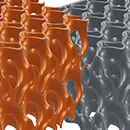
- Use lattice structures deliberately With elastic resins, the compliance of a part can be adjusted via a lattice structure – for example for cushions and dampers.
- Test under real conditions Test parts under realistic conditions before using them in series.
Limits & alternatives
When is another process the better choice?
- Post-processing Cleaning and post-curing are part of the process. You can see the current production times in the configurator.
- Part size The build space is limited. For larger parts, powder bed processes, for example, are an option.
- Support structures Supports must be removable, and resin must be able to drain from cavities. This somewhat limits the design freedom.
- Medical applications Some manufacturers’ datasheets mention tests according to ISO 10993 under defined process conditions. This is not an approval for a specific application; suitability must be clarified on a case-by-case basis.
| Process | Strengths | May be the better choice if … |
|---|---|---|
| Stereolithography (SLA) | Smooth parts with fine details, depending on the resin also transparent | … you need highly transparent parts or demonstration models |
| Laser sintering (SLS) | Robust parts without support structures | … your part is larger or should be made without support structures |
| Multi Jet Fusion (MJF) | Powder bed process without support structures, also with TPU | … you need functional parts without support structures |
| Material Jetting | Soft parts made of silicone-like printing material with fine details | … your soft part has very fine details |
| Injection molding | Cost-effective for large quantities | … the quantity is so large that a tool pays off |
Applications
What is the CLIP process used for?
CLIP produces functional prototypes and end-use parts: housings, brackets, clips and covers, parts with flame-retardancy requirements, jigs, fixtures and tooling aids – for example made of UMA 90, which the manufacturer describes as suitable for this – as well as elastic dampers and cushions.
Series production
Functional parts in small batches – without tooling, made from resins for technical use.
To series production
Prototyping
Functional prototypes made of engineering resins – to test form, fit and function early on.
To prototypingOrdering
How do I order CLIP parts?
Upload your 3D file, choose material and process and see the available offers.
- Upload file Upload your 3D data in the configurator. The system automatically checks whether the part fits into the build space.
- Choose material Choose from more than 160 materials and more than 12 processes – for example RPU 70 with the CLIP process.
- Check the offer As a rule, you immediately see the price and production time of the suppliers that can manufacture your part.
- Order You order directly online at the selected price.
FAQ
Frequently asked questions about the CLIP process
What is the CLIP process?
Continuous Liquid Interface Production (CLIP) is a 3D printing technology developed by the US company Carbon. A projector exposes liquid resin from below through an oxygen-permeable window, while the build platform continuously pulls the part upward. Many resins are then post-cured in an oven.
What is the difference between CLIP and DLS?
CLIP refers to the technology with the oxygen-permeable window and the dead zone. Carbon calls the overall process based on it – including the resins and post-curing – Digital Light Synthesis (DLS).
What is the difference between CLIP and SLA?
Both cure liquid resin with light. In SLA, a laser usually traces the cross-section layer by layer; in CLIP, a projector projects entire cross-sections, and thanks to the dead zone, the part grows continuously without having to be detached from the vat bottom after each layer. Many CLIP resins only reach their final properties through thermal post-curing.
Which materials are available for CLIP?
On the PROTIQ Marketplace, the current choice includes the epoxy resins EPX 82 and EPX 86FR, the polyurethane resins RPU 70, RPU 130, MPU 100 and FPU 50, UMA 90, Loctite 3D IND405 and the elastomers EPU 40, EPU 41 and SIL 30.
Why are CLIP parts post-cured in an oven?
Many CLIP resins are dual-cure: the UV light shapes the part, and a subsequent thermal treatment activates a second reaction. Only then does the part reach the properties stated in the datasheet. Some resins, such as UMA 90 or Loctite 3D IND405, do not need an oven.
Are there flame-retardant CLIP materials?
Yes. According to the datasheet, EPX 86FR achieves UL 94 V-0 at 2.0 mm and V-1 at 1.5 mm specimen thickness. The rating applies to standardized test specimens; whether your part meets the requirements must be checked on a case-by-case basis.
Are CLIP parts biocompatible?
This cannot be said in general. Some manufacturers’ datasheets mention tests according to ISO 10993 under defined process conditions. This is not an approval for a specific application; whether a part is suitable for a medical application must be clarified on a case-by-case basis.
How large can CLIP parts be?
That depends on the supplier’s machine. When you upload, the system automatically checks whether your part fits into the build space. If it is too large, please contact us.
How much does a CLIP part cost?
The price depends mainly on part volume, size, material and quantity. After uploading your file, you will usually see the suppliers’ prices immediately in the configurator.