

 Deutsch
 English
 Italiano
-
Manufacturing service
-
Manufacturing processes
-
Materials
-
Manufacturing processes
-
Other services
-
Knowledge area


Additive manufacturing of inductors: Economically reasonable and time-saving
Industrial production increasingly relies on additive manufacturing processes such as selective laser sintering (SLS), selective laser melting (SLM), stereolithography (SLA) as well as different buildup welding, stranding and particle deposition processes. The layer-by-layer construction of materials such as plastic, metal, ceramics, plaster and paper allows the fast and material-saving creation of individual components and thus the implementation of the core idea of Industry 4.0.
Additive manufacturing - also known as 3D printing - enables new degrees of freedom in product design. For example, complex geometries, functional elements, grid and support structures as well as internal geometries such as fluid guides can be produced cost-effectively, so that subsequent assembly can be simplified or even eliminated. Function integration allows several elements of an assembly to be combined into a single component as early as the generative process. However, the new design freedom poses a challenge for designers, most of whom have specialized in traditional, material-removing processes. With 3D printing, you are no longer bound in the design phase by the usual restrictions such as squareness, degree, flatness, roundness, parallelism and assembly accuracy. Instead, the use of free-form surfaces, undercuts, internal as well as support and grid structures allows for significantly increased component or product functionality as well as lightweight design concepts.
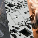
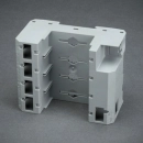
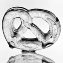
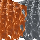
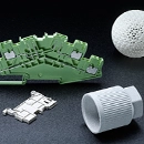
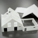
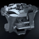
 Stress-optimized injection mold
Additive manufacturing consequently opens up more freedom in design, although design guidelines must be followed. In powder bed-based laser melting or sintering of metals and plastics, it must be ensured that the unmelted powder can be removed from the cavities. Furthermore, 3D printing of metal components requires support structures to absorb residual stresses, dissipate process heat and achieve high geometric accuracy. Post-processing of the produced components is an additional process step that is often performed manually and plays a significant role in determining manufacturing costs. This includes the removal of components from the unused powder, the removal of support structures and the reworking of functional surfaces. An AM-compatible design takes these aspects into account and is therefore a requirement for economical additive manufacturing.
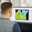
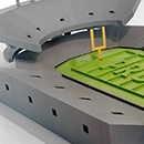
Optimization of geometries using application simulation
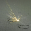
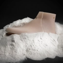
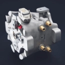
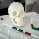
Induction heating is a popular heating method in the metal processing industry because it proves to be process-safe, energy-efficient and precisely controllable. For this purpose, an alternating current is applied to an induction coil so that a magnetic field is formed. If the user now brings a conductive component into the magnetic field, an electric current is generated. The component heats up to a defined target temperature by means of ohmic heating, whereby heating rates of over 150 K/s can be achieved. The basic prerequisite for high efficiency is the shape of the inductor used. The more precisely the inductor is adapted to the workpiece, the more efficient and homogeneous the heating. Traditionally, shaping is done by manual bending and soldering, which means that only relatively simple geometries can be produced due to the manufacturing process. Heating complex components is therefore usually accompanied by significant inhomogeneity and low efficiency.
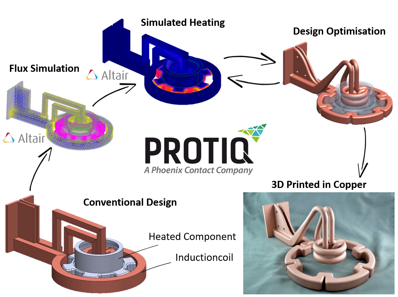
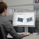
CAD-programs not only provide the models for 3D printing, but can also be used for process simulation of the finished 3D object. Magnetic simulation can be used to mimic the magnetic field of an inductor and the entire inductive heating process. Based on the data obtained, it is already possible to derive from the model how the component will behave in operation. It is also possible to see where heat losses or inhomogeneity occur because the magnetic field does not yet optimally enclose the workpiece to be hardened. Based on these results, the geometry can be optimized and the performance improved.
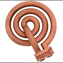
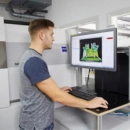
Online configuration of individualized components
However, the production of a customized inductor does not prove to be economical for every field of application. Many inductors are based on standard geometries. While delivery times of several weeks are common in conventional manufacturing, additively manufactured inductors are available after just a few days. Furthermore, experience shows that production costs are reduced by around fifty percent.
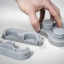
If a broken inductor causes a machine standstill, the user needs a replacement tool immediately. However, due to conventional, manual production, the geometries are usually only available as a 2D drawing and not as a CAD model. The 3D model must therefore first be built up in order to print the inductor. In the Protiq Marketplace inductor generator, heating coils can therefore be configured online for specific applications in just a few steps. First, the user selects a standardized basic shape whose dimensions can be adapted according to the modular principle. Parameters such as height, cross-section or the number of windings can be changed according to requirements. The inductors can then be optionally enhanced by adding a connector element, of which the dimensions can be freely selected. Even during configuration, a 3D model of the individualized geometry is created, and the price is calculated automatically. Additive manufacturing of the inductor can begin immediately after the order is received, so that it is delivered after just a few days.
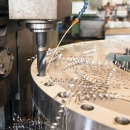
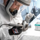
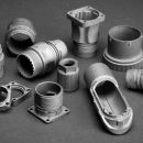
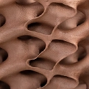
3D printing of highly conductive copper

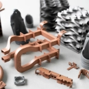
PROTIQ develops process for 3D printing of highly electrically conductive copper
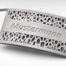
The processing of highly conductive copper is the first step that allows the production of inductors. In selective laser melting, metal powder is melted by a laser and built up layer by layer to form a 3D object. However, copper almost completely reflects the radiation of conventional laser melting systems, which makes selective melting of the material almost impossible. Therefore, Protiq has developed a process that nevertheless allows the processing of highly conductive, 100% pure copper as well as zinc and brass. As a supplement to the zinc die-casting process, small quantities can thus be manufactured additively from the zinc series material Zamak 5 during product creation or as spare parts. The processing of brass offers a new freedom of design for the jewelry or fittings industry.
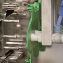
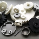
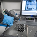
Development of an optimized plastic laser sintering system
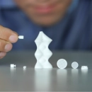
In laser sintering, the plastic components are built up layer by layer in three steps: First, a 0.06 to 0.12 millimeter thin layer of powder is applied. Then radiant heaters heat the powder to just below the melting point. Finally, a laser melts the layer-specific cross section of the component. When the process is complete, the finished component is surrounded by unmelted plastic powder. Traditionally, 90 percent of laser-sintered components are produced from PA 12 with or without fillers - such as aluminum or glass beads. However, the electrical or automotive industries demand engineering plastics that meet the requirements of the end products - for example, PA 6, PA 6.6 or PBT. In addition, the widely used standard plastic polypropylene (PP) and thermoplastic polyurethane (TPU) open up a wide field of applications.
In order to also manufacture series products directly and without tools, PROTIQ GmbH has developed an optimized laser sintering system. A precise control technology enables the processing of high-temperature plastics at a preheating temperature of up to 380°C. With an innovative powder application system, even poorly free-flowing powders can be processed, so that even cryogenically grinded standard granulates can be used in the material development process. In addition to new materials, the direct tool-free production of series components requires a high detail resolution with high build speed at the same time. New exposure strategies with adjustable laser spot implement these requirements. With a minimum laser spot diameter of 0.23 millimeters, filigree structures can be generated, while exposure with a laser spot up to 2 millimeters in size allows fast, economical production with high build rates.
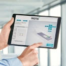
Automating the process chain
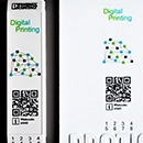
Until now, quoting and production planning as well as material handling and component rework have mostly been done manually. To prevent these upstream and downstream processes from slowing down the speed of additive manufacturing technology, an automated process chain is needed. Protiq therefore works with an online platform on which the customer can get his individual CAD model analyzed. He then immediately receives information about the manufacturing costs and delivery time. The customer then selects the production process, material and finishing - for example, painting in any RAL color. When the ordering process is completed, the manufacturability of the component is checked, possible errors in the model are corrected and production is then automatically triggered, with the customer being continuously informed about the current production status.
More News

Are your 3D files ready?
Just upload your data. All files are automatically checked and optimized for printing.


