Deutsch
 English
 Italiano
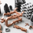


Threaded connections for 3D printed components
Screws are a common method of connecting components together. They are easily accessible and allow components to be separated without damage. With additive manufacturing, it is possible to simply 3D print threads as well – if a few points are taken into account.If two components have to be joined together, a screw connection is often the first choice. Compared to gluing or welding, the components can be separated again without damage and with the simplest of means. Furthermore, a screw connection is universally standardised and the screws and nuts are available everywhere as standard parts.
A screw connection represents a positive and non-positive connection in which the screw can generate a high contact pressure via its interlocking thread. The design of the screw thread and the mating thread has a great influence on the connection. The most common thread form is the metric thread. Its properties and geometry are the same everywhere and standardised.
Usually, corresponding threads are cut into an existing core hole in a component with the help of a thread cutter. The high design freedom of additive manufacturing offers the possibility to bypass these additional processing steps of thread cutting and to "directly print" a corresponding thread. However, some points must be taken into account here.
Production-ready 3D data preparation
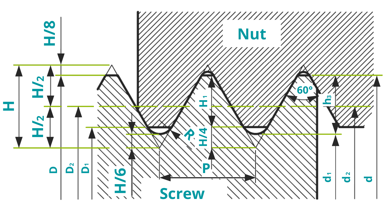
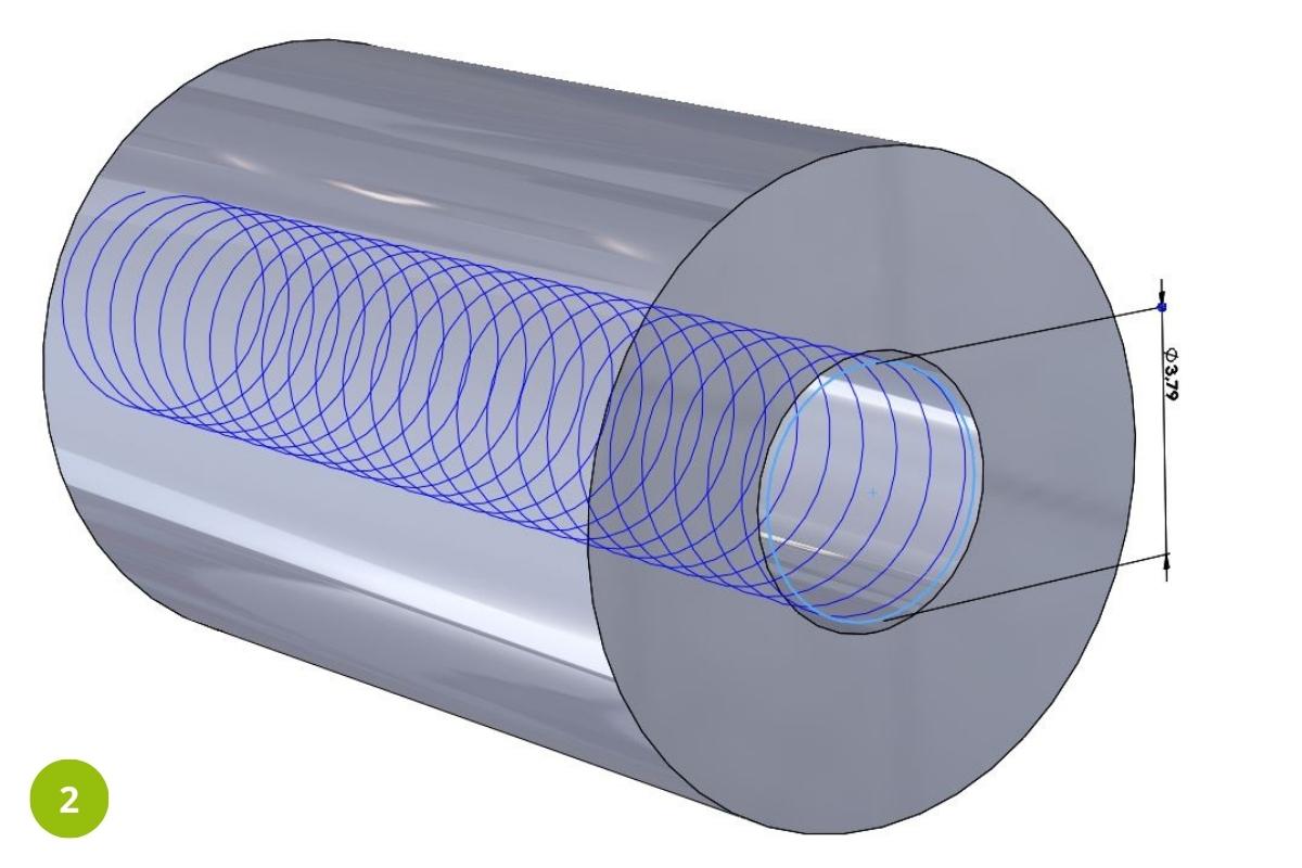
In order to produce a functional thread in 3D printing, it is essential to completely design its geometry. This is not the case with automatically created threads that have been defined with the help of conventional CAD programmes. For a complete representation, the procedure of deducting the corresponding geometry of a thread along a helix from an inserted core hole has proven itself.
Exemplary construction of an M5 thread:
- Core diameter (D1) = 4.134 mm,
- Flank diameter (D2) = 4.480 mm
- Height of the profile triangle (H) = 0.6928 mm
- Diameter of the helix (D2-H) = 4.480 mm - 0.6928 mm
- Pitch of the helix (P) = 0.80 mm
The corresponding dimensions of a metric thread according to DIN 13-1 can be found in the relevant literature or, for example, here.


Alternatives to the printed standard thread
In addition to the solutions of a classically cut and directly 3D-printed thread, there are also several alternatives. The different solutions are compared here.
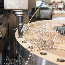
1. Pre-printing of the core hole and manual thread cutting
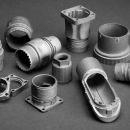
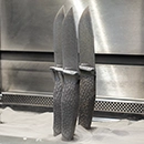
3D printed core hole, (diameter 4.1 mm), metric thread M5, cut with tap. This variant should be used for metallic components (SLM). However, it is also suitable for components from selective laser sintering (SLS).
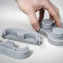
2. Constructed metric thread
Geometry of the threads already completely represented in the CAD file. Suitable for plastic components from the SLS or SLA process. For metallic components with 3D printed threads, these must be additionally recut. Suitable for minimum screw dimensions M3 (plastic), M8 (metal, with recutting).
3. Direct screwing in of metric threaded screw with defined core hole diameter
With plastic components from the SLS process, it is possible to screw metric threads into the material even without an existing thread. Tests have shown that a 3D printed core hole printed with a diameter 0.3 mm smaller than the screw diameter is best suited for this. (Example: M5 screw (5 mm) in 3D printed core hole with 4.7 mm diameter). Minimum screw dimensions M3. This variant does not work with metal or resin-based components.


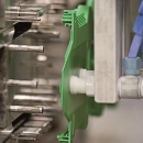
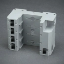
4. Pocket for steel nut
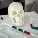
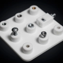
The simplest way to make a screw connection is to use a suitable steel nut. Both the screw and the nut are standard parts and therefore very inexpensive to purchase. In addition, the thread pairing of a steel screw and nut offers a very high strength that can be reliably calculated. Due to the possible design freedom of additive manufacturing, it makes sense to directly print a suitable pocket for the corresponding nut. In this way, the nut remains in position even when not connected. This variant can be used for all 3D printing processes. Particularly with components from the stereolithography process (SLA), this should be used, as the high thread forces are absorbed by the nut and not the component.
5. Sleeve for self-tapping wood screw/plastic screw
Plastic components from the SLS process can be screwed with self-tapping steel screws for wood or plastic. The screw is cut directly into a 3D printed core hole with the corresponding undersize. The diameters of the core hole differ depending on the type of screw and must be taken into account in the design. This connection is not suitable for components made using the SLS process, as the material is too brittle for the self-tapping screws.
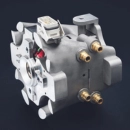
6. Press-in sleeve/ fusible sleeve
With thermoplastic components (SLS process), screw connections can be realised by inserting a metallic threaded sleeve. This sleeve is either pressed directly (cold) into a 3D printed core hole or melted into the thermoplastic. The threaded insert is carefully heated by a soldering iron to the melting temperature of the plastic and then pressed by the soldering iron into the softening core hole. After the sleeve and the plastic have cooled, the joint is ready for use. For resin-based SLA components, the sleeves should be glued in place, not pressed in or heated. Resin-based SLA parts cannot be melted by high temperatures, but only burn or carbonise!
7. ENSAT/Helicoil insert
With plastics, it is advisable to reinforce inserted threads with an ENSAT or helicoil insert. The insert is screwed into a larger thread. The corresponding core thread must be cut accordingly or designed before 3D printing. The resulting connection has a higher load-bearing capacity, as the weak plastic thread also has stronger threads due to the larger diameter used. In addition, the metal thread insert distributes the occurring screw forces more evenly over the weak plastic threads. This solution is suitable for all 3D printing processes and offers a possibility to repair damaged or torn out threads afterwards